Diagnostics and infusion platforms
Device history records per serial number, validated cleaning to 1.56 µg NaCl-eq/cm², biocompatible coating options under IPC-CC-830, and change control that requires customer sign-off before any process revision.
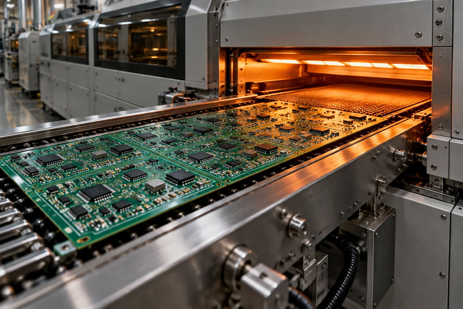
We take your Gerber set and BOM and return serialised assemblies: paste print, placement, reflow, through-hole solder, clean, inspect and test — all held to the same process of record whether the order is 5 boards or 45,000 a month.
A build starts at DFM review, not at the line. Our process engineers check your artwork against IPC-2221/2222 design rules and IPC-7351B land patterns, flag annular ring, stencil aperture and panel-utilisation problems, and return the annotated report inside 24 hours. Nothing is quoted as firm until that review is signed off.
From there we own the whole chain: kitting from a 12,000 sq ft ESD-controlled store holding 4,000 unique part numbers, laser-cut stainless stencils in 4 hours, 3D SPI on 100 % of boards, placement to ±35 µm at 3σ, twelve-zone nitrogen reflow, wave or selective soldering for through-hole content, inline aqueous cleaning verified to 1.56 µg NaCl-eq/cm², and electrical test before depanel.
Six SMT lines across two plants place 14 million components per month. Capacity is deliberately split: three volume lines in San Jose, one NPI and flex line for engineering builds, and two lines in Penang for programs that need a second site, a lower cost base or a regional customs position.
Quality is not a separate department. Every program carries an IPC-A-610 class assignment at quote stage — Class 2 or Class 3 — and that assignment drives the inspection plan, the operator instructions and the warranty terms. The quality system page lists the certificates we hold and the records kept against each board serial number.
Each row below is a real process boundary, not a marketing range. If your design sits outside one of them, tell us at RFQ stage and we will say so before you place a purchase order.
These are the numbers our equipment is qualified to hold, not the extremes of a datasheet. Anything at the edge of a row gets a capability study before we accept the order.
| Parameter | Window | Control method |
|---|---|---|
| Board size | 20 × 20 mm to 610 × 510 mm | Vacuum tooling and programme-specific clamps |
| Board thickness | 0.4 mm – 6.4 mm | Rail support and pin support per panel |
| Component range | 01005 (0.4 × 0.2 mm) to 55 mm connectors | Nozzle and feeder set per programme |
| Fine pitch | 0.35 mm BGA · 0.4 mm QFN · 0.3 mm CSP | 3D SPI plus post-reflow 3D AOI |
| Placement accuracy | ±35 µm chip · ±25 µm fine pitch @ 3σ | Daily glass-plate verification |
| Stencil | 0.10–0.20 mm laser-cut stainless, nano-coated | 4-hour turn from released Gerber |
| Solder paste print | 3D SPI on 100 % of boards, CpK ≥ 1.67 | Automatic print correction feedback |
| Reflow | 12-zone convection, nitrogen inerted | ±1.5 °C profile repeatability |
| Through-hole fill | 0.6–6.4 mm barrel fill | IPC-A-610 Class 2 and Class 3 criteria |
| Ionic cleanliness | ≤ 1.56 µg NaCl-eq/cm² | Inline aqueous wash, J-STD-001 test |
| Depanel | Router, laser, V-score, water-jet | Tab routing, 0.5 mm burrs removed |
Seven stations, in this order, on every surface-mount program. A board that fails a station is stopped at that station — it does not travel forward and it is not sorted out at the end of the line.
Gerber, BOM and fab drawing checked against IPC-2221/2222 and IPC-7351B. Annotated report returned in 24 hours.
Nano-coated stencil, 0.10–0.20 mm foil. 3D SPI measures volume, area and height; CpK ≥ 1.67 gates the panel.
Up to 30,000 pcs/hour per line, ±35 µm chip accuracy, 01005 through 55 mm connectors on the same programme.
Twelve convection zones with nitrogen, ±1.5 °C repeatability, profiled with thermocouples on every new panel design.
Inline 3D AOI after reflow; 2D and 3D CT X-ray for BGA, CSP, LGA and QFN voiding at or below 25 %.
Router, laser, V-score or water-jet. Tab routing leaves no burr above 0.5 mm and no cracked ceramic.
Custom fixture, ICT, flying probe or JTAG boundary scan, then serialisation into the MES record.
The gate thresholds below are written into the control plan for the program, so a deviation is a documented event with a disposition, not an operator judgement call. These six process gates sit inside the seven-gate quality system described on quality, which adds incoming component verification and bare-board receipt inspection ahead of the printer.
The process is common; the documentation layer is not. Each industry pulls an extra set of controls on top of the standard build.
Device history records per serial number, validated cleaning to 1.56 µg NaCl-eq/cm², biocompatible coating options under IPC-CC-830, and change control that requires customer sign-off before any process revision.
ITAR-registered handling, Class 3 workmanship as the default, first article inspection to the AS9102 report shape, and material traceability retained 10 years in the MES.
Control plans, PFMEA ownership, 400 A bus-bar soldering with thermal profiling, and PPAP-style documentation packages built from the same MES data used on the line.
Thick copper and heavy thermal mass handled with extended soak profiles, conformal coating for humidity and sulphur environments, and burn-in from 40 °C to 125 °C before shipment.
Heavy copper reflow, selective-soldered bus bars, creepage and clearance checks against IPC-2221, and high-pot testing on coated assemblies.
Line balancing across 6 SMT lines, 45,000 assemblies a month at peak, cost-down reviews after the first production run and DFM feedback that feeds the next hardware revision.
Numbers below are the current plant figures. They are reviewed monthly against actual MES output, and we will tell you which line a program would run on before you commit.
San Jose carries 42,000 sq ft with 150 staff and the NPI line; Penang carries 18,000 sq ft with 60 staff on two volume lines. Both sites run the same stencil thickness rules, the same reflow profile library and the same IPC-A-610 acceptance criteria, so a program can be moved between them without a new first article on the customer side.
One San Jose line is reserved for engineering builds and flex work: 38 programs are in NPI at any time, each with a named process engineer, a 15-working-day pilot slot after DFM sign-off and a dedicated fixture bay. Volume work does not queue behind prototypes.
The commercial shape of a program matters as much as the process window. These are the standing terms; anything different is negotiated in writing at quote stage.
| Item | Term |
|---|---|
| DFM review on a new BOM and Gerber set | 24 hours |
| Firm turnkey quote | 48 hours |
| Prototype PCBA, 5–50 boards, standard parts | 5–8 working days |
| Prototype with consigned or long-lead parts | 8–12 working days |
| NPI pilot run after DFM sign-off | 15 working days |
| Production repeat order | 3–4 weeks ARO |
| Turnkey ramp with full kitting | 4–5 weeks ARO |
| Stencil fabrication | 4 hours |
| Minimum order quantity | 5 boards |
| NRE on standard single-sided SMT | $0 |
| Fixture NRE credit | Credited at 5,000 units |
| Payment terms | Net 30 approved credit · Net 15 first order |
| Tooling ownership | Customer, after first article |
| Workmanship warranty | 12 months |
Stencils, test fixtures and programming belong to you once the first article is accepted, and we will release them to another supplier on request. Programs are held under NDA by default — no customer name or logo is ever published.
Send the BOM and Gerber set and we return a DFM report in 24 hours, then a firm turnkey quote in 48. Both come from the same engineer who will run the build.
Yes, and that is the point of the seven capability groups. A typical mixed-technology program runs print, place and reflow in San Jose, selective soldering on three robots, inline aqueous cleaning, 3D AOI, X-ray on the area arrays, functional test on a fixture we build, and final enclosure assembly — without the assemblies leaving our ESD-controlled floor. That removes the inter-supplier handling, re-packaging and re-test that normally costs a week of lead time and adds a failure mode at every handover.
We say so during the 24-hour DFM review, with the specific limit we would breach and the alternatives. A board larger than 610 × 510 mm, a component below 01005, a 0.25 mm pitch device or a press-fit connector outside our qualified force range all trigger a written capability note before quoting. If the gap is closeable with a panel change, a stencil change or a fixture, we price that instead of declining the program.
By default the program stays where it is first qualified. A move to the second plant is a commercial decision, usually for cost or regional supply, and it is done as a controlled transfer: same process of record, same control plan, a first article inspection at the receiving site, and no change to the part numbers you buy. Both sites sit inside our ISO 9001:2015 and ISO 13485:2016 certificates, and audits of either plant are welcome.
Send the BOM and artwork. You get an annotated DFM report in 24 hours and a firm turnkey quote in 48 — whether the first build is 5 boards or 5,000.