Consumer electronics PCBA: fast ramps without giving up yield
Consumer programmes are won and lost on the calendar. A board that reaches 25,000 units a month in month five is a different supplier decision from one that ramps in month fourteen, and getting there without a yield collapse means the pilot has to be built the way the production run will be built.
- Pilot to volume
- 50 pcs to 30,000/month
- Stencil turn
- 4 hours from Gerber
- Smallest part placed
- 01005 · 0.4 × 0.2 mm
- Cosmetic grade
- Class 2 with visible-joint criteria
The consumer trade-off is a calendar problem wearing a cost costume
Nobody in consumer electronics asks whether a board can be built. They ask whether it can be built at the target cost by the ship date, and whether the second build will match the first.
Cost per placement is the number that decides where a board is built. A design with 900 placements and a 60-second cycle is competing with every other programme on the same line, and the only levers that move it are panel utilisation, feeder count and the number of times the line stops. We quote the placement cost as a line item so the design team can see what a 12 mm keep-out around a shield can actually costs.
Time-to-market arrives second. A consumer programme usually starts with a 50-piece engineering pilot and needs 30,000 units a month within two quarters. If the pilot is built on a different line, a different stencil and a different profile from the volume run, the ramp relearns every lesson the pilot already paid for.
Cosmetic acceptance arrives third and is the most under-specified. Consumer products put the board in front of a customer through a transparent window or an open frame, so a joint that would pass IPC-A-610 Class 2 on an industrial board is a visible defect here. We agree a photographed cosmetic standard at first article rather than arguing about it at lot four.
The BOM arrives fourth, and it is designed to expire. A consumer board's active devices are commonly obsolete within 18 months of launch. The sourcing plan has to assume two alternates on every critical line and a re-qualification route that takes days rather than a quarter.
A 01005 chip is 0.4 mm by 0.2 mm and weighs almost nothing. It will tombstone on an asymmetric pad, and it will be blown off by an air knife applied a second too long. The aperture ratio matters more at this size than at any other: get the stencil wrong and no amount of placement accuracy recovers the yield.
What a consumer drawing actually demands from the line
Four requirements separate a consumer build from a general-purpose assembly, and each one changes a machine setting rather than a document.
| Requirement | Typical call-out | Line setting behind it |
|---|---|---|
| Miniature passives | 01005, 0.4 × 0.2 mm, alongside 0201 | Fine-pitch head at ±35 µm @ 3σ, nitrogen reflow, low-residue paste |
| Fine-pitch digital | 0.4 mm pitch QFN and 0.35 mm pitch BGA | ±25 µm @ 3σ on the fine-pitch head, 3D SPI on 100 % of boards |
| Chip antenna placement | Antenna feed centred to ±0.1 mm on the pad | Placement verified against a reference image at first article, not by eye |
| Flex and rigid-flex | Thin cores, stiffener bonding, panel handling | Reduced vacuum and panel support; depanel by laser or router to 0.5 mm burrs removed |
| Cosmetic solder criteria | Visible joints on an open-frame product | AOI recipe plus a photographed standard agreed at first article |
| Stack-up and thickness | 0.4 mm to 1.6 mm, 4 to 8 layers | Board window from 20 × 20 mm to 610 × 510 mm on the same line |
| Coating and appearance | Selective coat, no visible flux residue | Inline aqueous clean with an ionic result ≤ 1.56 µg NaCl-eq/cm² |
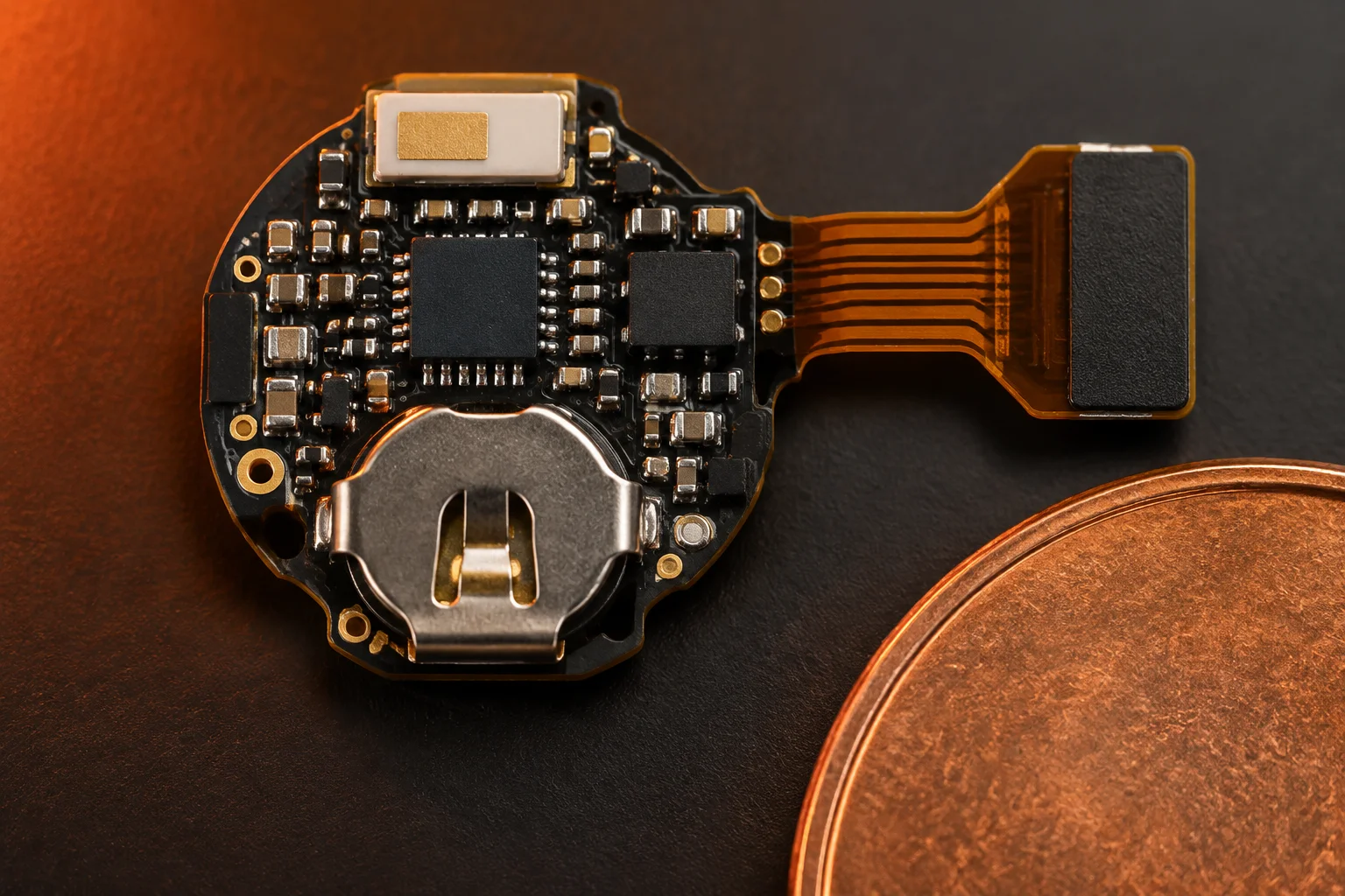 01005 placement · NPI line
Ramp mechanics: how a 50-piece pilot becomes 30,000 a month
A ramp is not a bigger version of the pilot. It is the same process run more often, and it only works if the pilot was set up that way.
Line balance comes first. We take the placement count, the feeder positions and the panel format and balance the two mounters against each other before the pilot is built, so neither head is waiting on the other for 20 % of the cycle. A board that runs at 60 seconds on the pilot line runs at 60 seconds at volume; a board that was never balanced runs at 90.
Feeder count is the second constraint. Consumer designs carry 4,000 unique part numbers across the programmes we run, and a single consumer board can need 180 feeder positions. If the design exceeds the positions available, the line stops for a reload mid-lot, which costs more than the part that caused it. DFM flags it in 24 hours, before the panel is committed.
Changeover is the third. High-mix consumer work lives or dies on how fast a line can move between programmes. We keep a dedicated NPI and flex line for the 5 to 500 unit releases so the three volume lines are never broken down for a pilot, and the stencil for a new revision is cut in 4 hours from released Gerber.
Then comes the transition package. The pilot lot leaves with a first article report, a golden sample, a control plan and the AOI recipe signed off, so the volume lot is verified against the pilot rather than against a fresh interpretation of the drawing. That single document is what stops a ramp from reintroducing a defect the pilot already fixed.
Sourcing that keeps up with a consumer schedule
A consumer ramp is usually decided by three lines of the BOM, and the sourcing plan has to be in place before the pilot, not after the launch date is announced.
Parts come from authorised or franchised distribution, never from the open market. That is what protects a consumer programme from a counterfeit reel turning up in month three, when the brand damage is already done. Suspect material follows AS6081-style handling and is quarantined on arrival.
Every critical active device gets a cross-reference assessed while the design is still open, with the packaging, tolerance and firmware implications written down. When a part goes on allocation, the approved alternate is a 24-hour action instead of a design review that costs the launch window.
Boards can leave in ESD bags with desiccant and a humidity card, in matrix trays for a downstream assembler, or in retail packaging with serialisation and firmware already applied. Packaging is chosen with the contract manufacturer who receives the boards, so nobody has to re-handle 45,000 units to fix a decision.
What actually moves the unit price
Four levers move the price of a consumer assembly more than any negotiation does. Three of them are decided by the designer, and one by the test engineer.
| Lever | What it changes | Effect on unit price | Where we can help |
|---|---|---|---|
| Panel utilisation | Boards per panel and rail area | Largest single lever | Panelisation review at DFM, rail width and breakaway method included |
| Layer count | Bare-board cost and yield | Direct, per layer | Stack-up review against the impedance and thermal requirement |
| Component count | Placements and feeder positions | Direct, per placement | Consolidation of values and packages where the design allows |
| Test coverage | Fixture NRE, cycle time, escape rate | Rises with coverage | Flying probe for the pilot, fixture for volume, coverage agreed per net |
| Cosmetic standard | Inspection time and rework rate | Rises with the standard | Photographed acceptance criteria agreed once, applied by AOI recipe |
| Change frequency | Stencil, profile and fixture re-work | Rises with each revision | Revisions batched, with tooling ownership with the customer after first article |
Test coverage is the lever buyers get wrong most often. A consumer board at 25,000 units a month cannot afford a fixture that never amortises, and it cannot afford to ship a defect that costs a retail return either. We price flying probe against in-circuit test against functional coverage at the actual volume, and the arithmetic usually points at a fixture once the programme passes 5,000 units in total. Fixture NRE is quoted separately and credited at 5,000 units.
The paperwork a consumer programme still needs
Consumer work is fast, but it is not undocumented. A retail launch carries material declarations, traceability and change control like any other programme.
- First article report with X-ray and dimensional data on the pilot lot
- Certificate of conformance and the workmanship class built to
- RoHS 2011/65/EU and REACH SVHC declarations per assembly
- Serial-number or lot-level traceability retained for 10 years
- Photographed cosmetic standard, dated and revision-controlled
- Conflict-minerals due diligence under the OECD framework and SEC 13p-1
Workmanship follows IPC-A-610 Class 2 unless a customer specifies Class 3, soldering follows J-STD-001, rework and repair follow IPC-7711/7721, and every operator handling the boards works inside an ANSI/ESD S20.20-2021 programme. The plant holds ISO 9001:2015 as its base system, with ISO 13485:2016, IATF 16949:2016 and AS9100D available for programmes that need them.
Laminate recognition covers UL 796 and UL 94V-0, which is what a retail safety submission asks for. Ultraviolet-curable and acrylic coatings are applied to IPC-CC-830 where the product needs one. Certificate copies and audit reports are released under NDA — no customer name, logo or part number is ever published.
A wearable board that went from 200 to 25,000 units a month in five months
A wearable brand in the Pacific Northwest came to us with a pilot of 200 units and a retail window five months out. The design was already frozen; the schedule was not.
The assembly is a 0.8 mm, 6-layer board with 01005 passives, two 0.4 mm pitch QFNs, a chip antenna and a rigid-flex tail. The pilot had been built elsewhere and had run at a first-pass yield the customer described as workable for 200 units and hopeless for 25,000.
What we changed: the panel was re-laid out for utilisation and the rail width reduced, which took the boards per panel up and the placement cost down; the chip antenna feed was centred against a reference image at first article; the AOI recipe was rewritten with a photographed cosmetic standard for the joints visible through the open frame; and the profile was moved to nitrogen to hold the 01005 tombstone rate down.
The ramp went 200 units in month one, 3,000 in month two, and 25,000 a month from month five. The stencil and the test fixture are owned by the customer, and the programme is still running on the same line with the same profile two years later.
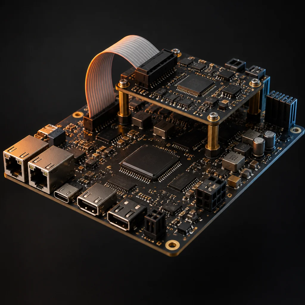 Wearable assembly · 01005
Questions consumer brands ask before the pilot
Yes, if the standard is photographed and agreed before the first volume lot. IPC-A-610 tells an inspector whether a joint is electrically and mechanically acceptable; it does not tell them whether a slightly dull fillet will be seen through a transparent housing. We build the cosmetic criteria into the AOI recipe and into a dated reference board kept at the line, so the fourth lot is inspected the same way as the first. Without an agreed standard the argument moves to rework, which is the most expensive place to have it.
Through our box-build and integration cell, yes: firmware flashing, serial-number and label application, retail carton and accessory kitting, and mixed configurations inside one lot where the SKU differs only by firmware or by a regional accessory. The firmware image is held under the customer's control and released per build, with the version recorded against the serial number so a field question about which firmware shipped on which unit has a data answer.
We run build-level mechanical verification — first-article dimensional reports, torque control on threaded hardware, and vibration or drop screening through a partner test house — and we will build the units and the fixtures the test needs. We are not an accredited mechanical test laboratory and we will not issue a drop-test certificate. What we do is make sure the assembly that goes into the test is the assembly that will ship, including the underfill, the staking and the stiffener bonding, because a reliability result from a hand-built sample is worth very little.
Send the Gerbers and the date you have to hit
Give us the launch window with the BOM. DFM in 24 hours, a firm quote in 48, and a pilot built on the line that will run the volume.