Automotive and EV electronics: IATF 16949:2016 and PPAP-ready builds
A vehicle board is qualified before it is bought. We build under IATF 16949:2016 on an ISO 9001:2015 base, hold the -40 °C to +125 °C window, run AEC-Q100 and AEC-Q200 parts unless the programme documents an exception, and produce the PPAP level 3 evidence a launch gate asks for — with serialisation tight enough to bound a recall to a date range.
- Quality standard
- IATF 16949:2016
- Launch evidence
- PPAP level 3
- Operating window
- -40 °C to +125 °C
- Part policy
- AEC-Q100 and AEC-Q200
- Traceability
- Unit serial, lot and date code
- Record retention
- 10 years
What changes when the board goes into a vehicle
The assembly does not get harder to place. It gets harder to keep alive: the thermal window widens, the mechanical loads stop being gentle, and every decision becomes a recall-scope decision.
Temperature is the first change. A board that lives in a sealed enclosure at room temperature is a different object from one that cycles between -40 °C and +125 °C over its service life. The failure modes move away from placement defects and toward solder-joint fatigue: a large-mass component with an unmatched thermal coefficient of expansion will crack a joint long before the paste print goes out of control.
Thermal shock on large mass is the second. A power stage, a transformer or a connector that takes seconds to reach reflow temperature while the surrounding laminate is already cooling creates a local thermal gradient. That is a design and a profile problem together, which is why the reflow profile is developed against the actual assembly, not against a bare board, and why the profile is re-run whenever the thermal mass changes.
Vibration is the third. A connector that passes a pull test can still fail a vibration profile if it is not mechanically supported. Staking, underfill and mechanical retention are specified in DFM, not added after a validation failure.
Part policy is the fourth. Automotive programmes expect AEC-Q100 for integrated circuits and AEC-Q200 for passives. Where a part is not qualified to those standards, the deviation has to be documented and justified by the customer's own engineering release — we will not quietly substitute a commercial-grade part to protect a lead time.
Traceability for recall scope is the fifth, and it is the one that costs the most when it is missing. Unit-level serialisation with material lot and date code linkage means a suspect component lot maps to a finite list of serial numbers, not to a date range of shipments.
We will not take on automotive safety-critical production without an approved PPAP file behind it. The evidence is the deliverable, and the boards are the by-product.
- Operating window
- -40 °C to +125 °C
- Chamber screening
- 40 °C to 125 °C
- Board thickness range
- 0.4 mm to 6.4 mm
- Maximum board size
- 610 × 510 mm
- Placement accuracy
- ±35 µm at 3 sigma
- Void limit
- 25 % per IPC-A-610
The build requirements behind an under-hood assembly
Every row below is a routing decision and a record. Where a programme tightens a limit further, the tighter limit is written into that programme's control plan and can only be changed by a documented change order.
| Requirement | Specification held | How it is verified | Record produced |
|---|---|---|---|
| Board thickness | 0.4 mm to 6.4 mm, heavy copper and mixed stack-ups included | Incoming laminate certificate plus drill and routing verification | Laminate certificate with UL 796 recognition |
| Bus current | Copper weight specified per net from the continuous current; a 400 A bus is not a default-foil problem | Cross-section on the first article plus thermal imaging under load | Cross-section images and thermal record |
| Thermal via arrays | Filled or plated thermal vias under the power stage, sized to the copper area each net carries | X-ray slice review and void measurement against the 25 % limit | X-ray void data in the first-article report |
| Underfill and staking | Underfill on fine-pitch and large-mass devices; staking on connectors and tall components | Dispense weight check and visual coverage inspection | Underfill and staking record per lot |
| Potting compatibility | Residue and coating chemistry declared against the potting compound the customer specifies | Material declaration review during DFM plus cleanliness verification | Material compatibility statement |
| Thermal cycling | Qualification support across the -40 °C to +125 °C window | Chamber screening from 40 °C to 125 °C with a logged ramp and dwell, plus partner HALT and HASS runs | Chamber run log and functional result |
| Workmanship | IPC-A-610 Class 2 as standard, Class 3 where the programme specifies it | 3D AOI after print, after reflow and post-depanel, with X-ray on BGA and QFN | AOI and X-ray data per unit serial |
| Traceability | Unit serial bound to component lot, date code and process data, 10-year retention | MES record written on the line, IPC-1782-style structure | Traceability record per serial |
What we produce for a launch gate
PPAP is not a document we write at the end. Four of its elements are by-products of running the programme properly; the fifth comes from the measurement system you specify.
Elements we produce
- Process flow diagram matching the routing actually used on the line
- PFMEA input from the process engineer who owns the build
- Control plan listing every gate, limit and reaction
- Dimensional results from first-article inspection
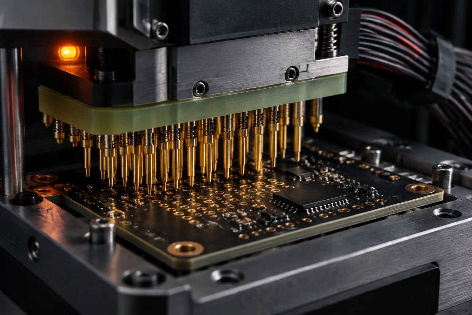
- Functional test results per serial, with the fixture and program revision
- MSA on the measurement systems we control, where the programme specifies it
How it is kept current
A PPAP file that describes last year's process is worse than no file, because it is evidence that is not true. Every element above is reissued when the process, the material, the fixture or the manufacturing site changes, and the revision history is part of the record. Layered process audits verify that the control plan on the wall matches what the line is doing; a mismatch is a non-conformance against us, not against the operator.
The control set that holds a ramp together
Automotive programmes fail at volume, not at prototype. The controls below exist to make the ten-thousandth unit behave like the fifth.
Error-proofing comes before inspection. Fixtures are keyed so a board cannot be loaded the wrong way round, programs are locked to a revision, and a build cannot start on a work order whose first article has not been signed. The reaction plan for a failed gate is written before the gate runs: what stops, who is told, what containment applies to material already produced, and what evidence closes the non-conformance.
Layered process audits run on a fixed cadence, checking the control plan against the line rather than the paperwork against itself. Change notification is written and issued before implementation — a process, material, fixture or site change on an automotive programme is a customer-facing event, and the PPAP file is reissued with it.
When volume grows, the second site is not an emergency. The Penang plant runs two SMT lines and can be qualified against the same control plan, which gives a programme a second source without a second supplier relationship.
From a 500-board pilot to 20,000 units a month
A ramp is a line-qualification exercise, not a quantity change. Here is how the volume stages are separated and what has to be true before each one starts.
-
Stage one · 5 to 500 boards
Pilot on the NPI line
The dedicated NPI line handles 5 to 50 engineering samples in 5 to 8 working days on standard parts, then a pilot run of up to 500 units 15 working days after DFM sign-off. First article, functional test fixture and the PPAP elements are produced here, on the line that will not be running production volume.
-
Stage two · 500 to 5,000 units
Line qualification
Before volume starts, the volume line is qualified against the same control plan used in the pilot: SPI gate at a CpK of 1.67 or better, AOI after reflow and post-depanel, X-ray on BGA and QFN with voids at or below 25 %. Any difference in equipment between the pilot line and the volume line is treated as a process change and re-validated.
-
Stage three · 5,000 units and up
Volume with a second site option
Volume production runs on the three dedicated lines in San Jose, with the Penang plant available as a qualified second site. Combined capacity is up to 45,000 board assemblies a month across 6 SMT lines and 2 plants, at a placement rate of 30,000 components an hour per line.
-
Ongoing
Change control and reissue
Change notification goes to the customer before implementation, and the PPAP file is reissued with it. A production repeat order under an existing programme has no minimum order quantity and runs 3 to 4 weeks ARO; a turnkey ramp with full kitting runs 4 to 5 weeks ARO.
A BMS board for an EV charger maker, 400 A bus
Anonymised as required. No customer name, no product name, no part numbers — the constraints are the useful part.
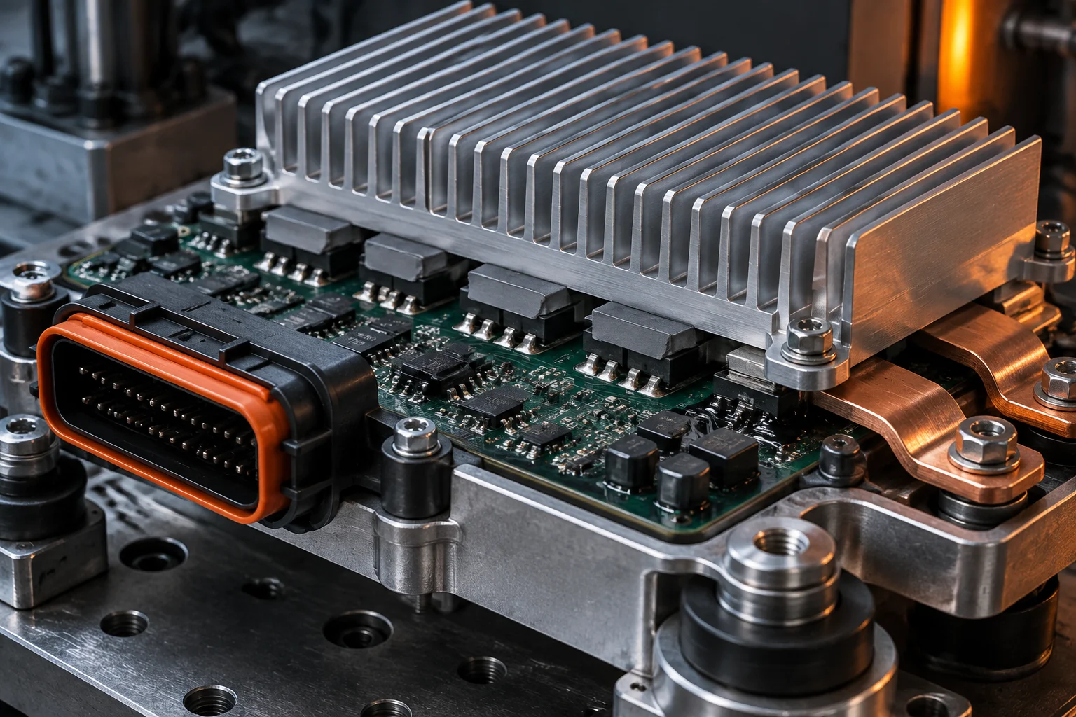
A charger manufacturer needed a battery-management board carrying a 400 A bus, with a heat sink bolted over the power stage and bolted bus-bar connections at the edge of the board. The first engineering conversation was not about placement; it was about where the heat goes and how the joints survive it.
DFM work covered the copper weight required per net, thermal via arrays under the switching devices, and the solder volume needed on the large pads where a partial fill would leave a void above the 25 % limit in IPC-A-610. Bus-bar attachment moved to selective soldering with a pallet designed around the thermal mass, and the bolted joints got a torque specification with thread-locking rather than a best-practice note.
Verification was thermal imaging under load, hipot and isolation-resistance testing on every unit, and a current-cycling sample plan on the first lots. The launch package included the PPAP level 3 elements, the control plan and a functional test fixture that logs the serial number on every board. Volume runs at 20,000 units a month, and the Penang plant is qualified as a second site against the same control plan.
A 400 A bus on a board that also has to pass a thermal cycle and hold its isolation. Copper weight, thermal vias, solder volume and torque control all had to be settled in DFM, because none of them can be inspected in afterwards.
Questions automotive buyers ask us
We supply the material data: every component, coating, adhesive, underfill and staking compound in the build, with its RoHS 2011/65/EU and REACH status and SVHC content below 0.1 % w/w, taken from authorised-distribution declarations rather than from a catalogue page. The assembly-level IMDS entry is normally filed by the customer or the tier-one, because the entry describes the part number they own. Tell us at DFM if you want the data in an IMDS-ready export and we will format it that way from the first revision.
Due diligence follows the OECD framework, and smelter reporting is available on request against the bill of materials for your programme. We source from authorised or franchised distribution only, which is also the basis of our counterfeit-avoidance practice, and country-of-origin data is recorded per component lot so the report is generated from the build record rather than from a supplier questionnaire.
It is a material-selection constraint, so it belongs in DFM. We declare the substances in every coating, adhesive and laminate we add to the board and hold SVHC content below 0.1 % w/w, which keeps the recyclability and material data your ELV submission needs traceable to a documented source. If a programme has an exemption, we keep the exemption file with the build record for 10 years so the evidence does not have to be reconstructed later.
Send the Gerber set and the launch date
Tell us the PPAP level you need and the thermal window you are qualifying against. DFM review comes back in 24 hours, a firm quote in 48, and the evidence pack is scoped before the pilot run is scheduled.