Box build, harness and system integration
Assembled boards shipped as a tested, labelled, sealed product: harnesses crimped and pull-tested to IPC/WHMA-A-620, enclosures machined and gasketed to IP67, firmware flashed under configuration control, and every unit traceable by serial number.
- Integration level
- Level 3 to level 5
- Harness workmanship
- IPC/WHMA-A-620 Class 2 / 3
- Enclosure work
- Machining, coat and anodise coordination
- Sealing
- IP67 gasket assemblies
What level 3, level 4 and level 5 actually mean
The levels describe how much of the finished product sits inside one supplier's scope. Buying more level than you need adds cost and locks in a supplier; buying less leaves integration work that nobody has quoted.
| Level | Scope | Test performed | Choose it when |
|---|---|---|---|
| Level 3 — board | Assembled, inspected and tested printed circuit board assemblies, ESD packed | AOI, X-ray and functional test at board level | You do your own mechanical build and final test |
| Level 4 — sub-assembly | Boards mounted on a chassis, plate or heat sink with harnesses and connectors fitted | Board test plus continuity, hipot and a functional check of the sub-assembly | A module ships into your own larger enclosure, or into a customer's rack |
| Level 5 — top-level box | The complete unit: enclosure, cable assemblies, labels, firmware, accessories and retail or field packaging | Full functional test on the finished unit, safety and sealing checks, cosmetic inspection | The unit ships straight to a distributor, an installer or an end user |
Integration at level 5 concentrates change control in one place, which shortens the path from a firmware change to a shipped unit. It also means any late engineering change touches packaging, labels and documentation, not just a board. Programmes with a fast revision cadence often stay at level 4 and integrate at their own site until the design stabilises.
Wire harnesses built to a documented crimp specification
Most field failures in a box build start at a crimp or a strain relief, not on the board. The harness is built to a drawing, tested electrically, and recorded wire by wire.
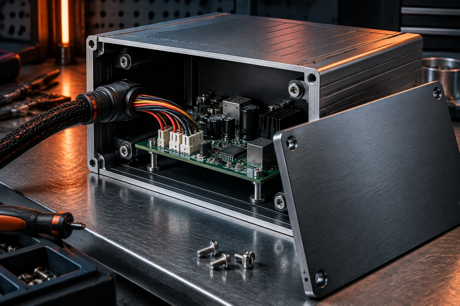
Every crimp is made with a calibrated tool and the correct die for the terminal and wire gauge, and the pull force is checked against the terminal manufacturer's table at the start of the run and at a defined interval afterwards. Crimp height, insulation strip length and bell-mouth are inspected under magnification; a crimp that passes a pull test but shows a cut strand is still a reject.
Workmanship follows IPC/WHMA-A-620 for the class on the drawing: strand damage, insulation support, contact seating, bend radius and cable tie tension all have written acceptance criteria. Wire IDs, colour codes and connector keying are checked against the drawing before the harness leaves the bench.
Each harness then runs on a continuity and hipot test board that checks every point-to-point connection and verifies insulation between circuits at 1,500 V AC for 60 s. The test program is written from the same net list the harness is built from, so a drawing error shows up as a test failure instead of a field return.
Mechanical integration from bare sheet metal to a sealed unit
Enclosure work is where tolerance stack-up decides whether a connector seals and a lid closes without preload on the board.
Cutouts, threads and inserts
Connector cutouts, display windows and mounting holes are machined to the drawing with position tolerances held at ±0.1 mm, and threaded inserts or clinch nuts are installed so a field technician can torque a fastener repeatedly without stripping the panel.
Powder coat and anodise coordination
Powder coat is applied at 60 to 120 µm and anodising at 10 to 25 µm, with masked areas named on the finish drawing. Coating thickness matters functionally: a masked grounding boss or a connector flange that gains 100 µm no longer fits the mating part.
Gaskets, glands and IP67
Sealing relies on controlled compression, not on force. Gasket grooves are sized for 25 to 40 % compression of the cord or moulded seal, cable glands are matched to the cable jacket diameter, and the finished unit is checked for IP67 sealing before release.
Fasteners are tightened with calibrated torque drivers to the value on the assembly drawing and, where the joint can vibrate loose, with a specified thread-locking compound or a mechanical locking feature. Torque values are recorded per station, and a driver that drifts out of calibration is removed from the line rather than adjusted on the fly.
Where the customer already owns the enclosure tooling, we integrate their parts and report any fit issue with measurements before modifying anything. Where the enclosure is ours to coordinate, the same supplier set carries from prototype through production so the finish and the fit do not change between the pilot and the ramp.
Thermal and mechanical verification before the design freezes
A box build adds interfaces that no board-level test can evaluate: heat paths, fastener preload, cable strain and enclosure rigidity.
| Check | Method | Acceptance |
|---|---|---|
| Heat-sink interface | Interface pad or thermal compound fitted to drawing, then thermal imaging under load at maximum ambient | Component case temperature inside the derating limit at 125 °C ambient, with pad compression verified on a sectioned sample |
| Dimensional first article | Full dimensional report on the first unit, including connector positions, panel flatness and lid gap | Every dimension inside the drawing tolerance, with the measurement method stated per feature |
| Vibration | Swept sine or random profile applied with the unit powered and monitored | No discontinuity, no fastener movement and no change in functional test result after the sweep |
| Drop and handling | Packed and unpacked drop from the height defined by the shipping specification | No deformation that breaks sealing, no cracked solder joint on a re-test, packaging intact |
| Cable strain | Pull and bend applied to every external cable at the gland or strain relief | No conductor movement at the terminal and no change in continuity resistance |
Verification results are delivered with the first article. When a change moves a connector, a heat path or a gasket, the affected checks are repeated rather than assumed.
One serial number, one configuration, one record
A finished box carries more configuration than a bare board: firmware version, label content, accessory kit and packaging variant all have to match the purchase order.
Each unit receives a serial number that links the board serial numbers inside it, the harness lot, the firmware version and checksum, the test record and the operator at each station. That record is retained for 10 years, so a unit returned from the field can be rebuilt in documentation without opening a dispute about what was shipped.
Labels are printed from the work order rather than taken from a shelf, which is what prevents a mixed lot: the label, the configuration file and the firmware image are all keyed to the same part number and revision. Firmware is flashed from a controlled image with a checksum verification after programming, and the version is recorded against the serial number.
Packaging is part of the release. Units are kitted with the accessories listed on the order, packed for the shipping method, and labelled with the handling and warning marks the specification calls for. Retail and field-install variants use different cartons from the same controlled packaging document.
| Item | Recorded value |
|---|---|
| Board serial numbers | One to many, with reel-level traceability |
| Firmware | Version, checksum and programming date |
| Harness lot | Crimp tool, wire lot and test result |
| Label and packaging revision | Drawing revision from the work order |
| Functional test | Pass or fail, limits version and station |
A DIN-rail controller shipped as a sealed top-level box
An industrial automation customer moved a motor-drive controller from board-level supply to a complete unit, and the change moved more than the enclosure.
The board had been shipping at level 3 into the customer's own cabinet build. Moving to level 5 pulled the harness, the DIN-rail housing, the front-panel label and the firmware flash into one work order, and it exposed two problems the customer had been absorbing: a connector cutout that needed 0.4 mm more clearance for the gland, and a heat-sink pad that compressed unevenly because the lid stood off the chassis.
Both were fixed at first article with a dimensional report and a thermocouple run at full load. Field returns over the following year were dominated by cable strain at the gland, so the strain relief was redesigned and the affected assemblies were re-verified by hand at the station before release.
A level 5 box build carries NRE for the fixture, the label artwork, the packaging drawing and the firmware release process. Those costs are quoted separately and credited at 5,000 units against the programme, and the customer owns the fixtures and the test program after first article.
Integration questions that come up at the quote stage
Yes. Send the enclosure drawing, the finish specification and the mating connector list. We measure the first delivery of housings against the drawing, report any deviation before we commit to a build date, and treat the enclosure as customer-supplied material on the record — counted, inspected and stored like any other line on the BOM. If the enclosure needs machining or a gasket change, we quote that separately so the cost is visible rather than buried in assembly labour.
You do. We hold the released image under access control for as long as the programme runs, flash it from a version-locked file, verify the checksum after programming and record the version against the unit serial number. Your file is never shared, never reused on another programme, and is returned or destroyed on request at the end of the programme.
It can, if the differences are declared on the purchase order and visible in the record. A mixed lot is built as separate sub-lots with their own serial number ranges, labels, firmware versions and test limits, then packed so a carton never contains two configurations. What we will not do is build two variants from one work order and rely on an operator to sort them at packing.
Send the assembly drawing, the enclosure drawing and the firmware release.
We will return the integration level we recommend, the fixturing and packaging NRE, the sealing and verification plan, and a firm price inside the 48-hour quote window.