Energy storage and power electronics: heavy copper, isolation and high-current safety
A battery-management board is a thermal and mechanical product that happens to have electronics on it. Every decision on the line — foil weight, solder volume, busbar attachment, creepage distance — is settled by how much current flows continuously and how much voltage stands between the pack and the person touching the enclosure.
- Bus current built to
- 400 A continuous
- Copper weight window
- 70 µm to 210 µm
- System isolation
- 1,000 V DC class
- Creepage target
- 8 mm at the barrier
Why a BMS board is not just a control board with thicker traces
On a storage rack the current never stops. A 400 A bus at 25 °C ambient is a slow, permanent heat source, and a board that is electrically correct can still fail because of where the heat lands.
Continuous current is the first difference. A motor drive draws current in bursts and averages far below its peak; a storage rack sits at 200 A to 400 A for hours during a charge or discharge window. The copper under the shunt and the MOSFET bank reaches a steady state rather than a transient one, so the design has to be judged on thermal resistance, not on ampacity tables alone.
Hot spots hide under the solder mask. A 210 µm copper plane spreads heat well and then traps it: the surface looks uniform under a camera while the laminate below the shunt runs 30 °C hotter than the plane beside it. We verify with thermal imaging under load rather than a simulated model, because the simulation does not know how the via array was actually drilled.
Isolation barriers decide whether the product can be sold. On a 1,000 V system the clearance between the high-voltage bus and the low-voltage communication side is a safety distance, not a layout preference. It has to survive the coating process, the conformal coat, the mounting hardware and the enclosure hardware that a field technician will drop onto the board.
Connector thermal rise is the fourth constraint and the easiest to miss. A terminal rated for 400 A on a bench can reach its temperature limit when it is bolted to a 70 µm pad with a 12 µm plating thickness. We specify, measure and record the rise rather than accept a datasheet number.
Heavy copper does not reflow like 35 µm foil. The thermal mass of a 210 µm plane pulls heat out of the joint faster than a standard profile delivers it, so large pads need a longer soak, a higher peak and a controlled ramp. We profile heavy-copper assemblies on the actual panel, with thermocouples attached, rather than reusing the profile from the last programme.
The electrical and mechanical call-outs that set the build
These are the lines a storage or power-conversion drawing usually carries. Each one maps to a process decision we make before the first panel is ordered.
| Requirement | Typical call-out | Process consequence |
|---|---|---|
| Copper weight | 2 oz to 6 oz on the bus layers (70 µm to 210 µm) | Adjusted reflow profile, longer soak, thermocouple-verified peak |
| Thermal via arrays | Filled and capped vias under the power stage | Via fill before plating; X-ray on every thermal pad |
| Busbar attachment | Bolted or soldered bar carrying 400 A | Selective solder or press-fit, then torque recorded to specification |
| Fuse and shunt placement | Kelvin-connected shunt, fuse within 20 mm of the terminal | Placement accuracy ±35 µm so the sense pair stays symmetric |
| Clearance and creepage | 1,000 V DC system, 8 mm across the barrier | Coating keep-out enforced; hipot on 100 % of assemblies |
| Solder volume on large pads | No voiding above 25 % on thermal interfaces | Stencil aperture and foil thickness chosen per pad, not per board |
| Battery-adjacent materials | RoHS and REACH declarations | Material declarations held per assembly, not per supplier |
| Transport packaging | Lithium-containing assemblies shipped with state of charge declared | ESD bag, desiccant, humidity card and a declared SoC on the packing list |
Assembly constraints that appear once the foil gets heavy
Heavy copper changes the print, the reflow and the solder volume at the same time. The three have to be solved together.
A 210 µm plane is rarely flat after lamination. We use laser-cut stainless foil from 0.10 mm to 0.20 mm with nano-coating, and hold the print to a 3D SPI gate of CpK ≥ 1.67 on 100 % of boards so a low deposit on a power pad is caught before reflow rather than at functional test.
Thermal pads and busbar footprints are sized for volume. We calculate the required deposit from the pad area and the joint geometry, then open the stencil aperture to suit instead of raising squeegee pressure, which only forces paste under the stencil and creates bridging on the fine-pitch side.
Busbars and 55 mm terminal blocks go through selective soldering with nitrogen inerting rather than a wave, so the SMT side never sees the pot. Hole fill is verified from 0.6 mm to 6.4 mm to IPC-A-610 Class 2 or Class 3 criteria, and every bolted joint is torqued to a recorded value.
High-voltage assemblies are washed and tested rather than left no-clean. Ionic contamination is held to ≤ 1.56 µg NaCl-eq/cm² per J-STD-001, because residue across an 8 mm barrier is a leakage path that a hipot test at production voltage will not always reveal. The result travels with the lot record.
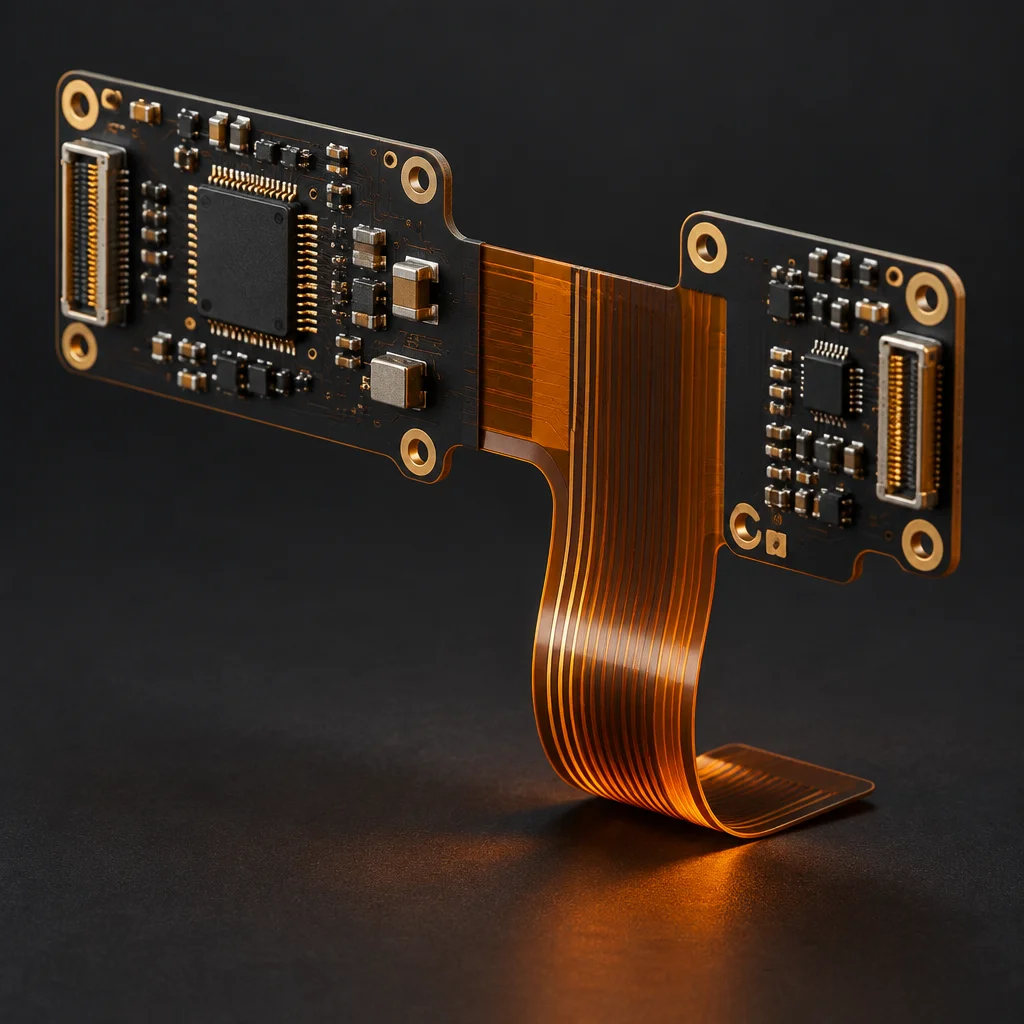 Thermal verification under load
Verifying a board that carries current for hours
A functional pass at room temperature proves almost nothing about a power assembly. Three checks do.
Thermal imaging under load comes first. We run the assembly at its rated continuous current, image the board from the component side with the enclosure in place, and record the peak surface temperature. A 400 A bus that holds under 25 °C rise is a different product from one that holds under 60 °C, and only the measurement tells you which one you have.
Hipot and isolation resistance come second. Every assembly is tested at the barrier before coating release and again after, because the coating process can pull the surface distance down if a keep-out was misprogrammed. Insulation resistance and leakage current are recorded as lot data, so a drift over months of production is visible rather than discovered in the field.
Current cycling comes third and is sampled rather than run on every unit. A sample from the pilot lot is cycled between full charge and full discharge current with the board instrumented, which is the only test that reproduces the thermomechanical fatigue that a bolted busbar joint actually experiences over a 10-year service life.
Because the voltage class is lethal, the test operations themselves are engineered: guarded fixtures, forced-discharge routines before handling, and a two-person rule on hipot stations. Test safety is a production requirement, not a suggestion.
The safety and compliance questions that arrive with the drawing
A storage rack is certified as a system, but the board inside it has to hand the system integrator the evidence they need. Four items come up on every programme.
Behind those four sit the plant-level systems: ISO 9001:2015 as the quality base, ANSI/ESD S20.20-2021 for handling, IPC-A-610 for the workmanship class, J-STD-001 for the soldering process, IPC-7711/7721 for rework and 10-year record retention for traceability. Certificate copies go out under NDA; we do not publish certificate numbers.
A 400 A BMS board for a commercial storage rack
A rack integrator brought us a battery-management board in 2022 after two suppliers failed the hipot stage on a 1,000 V system during ramp.
The board is 2.4 mm thick with 140 µm copper on the bus layers and a 400 A bolted busbar at the pack terminal. The failure they arrived with was not electrical: the coating process on the previous supplier's line had bridged a barrier keep-out, and the isolation resistance drifted below the limit after coating rather than before it.
What changed on transfer: the coating keep-out moved into the programmed spray path, hipot was moved to after coating on 100 % of units instead of sampling, and the busbar joint went to a torque-recorded process with the tool calibration logged per shift. The first article included a thermal image at rated current and a set of cross-sections through the via array under the power stage.
Volume runs at 1,200 boards a month with a second-site option in Penang for the European shipments. Every unit is serialised before it leaves the line, and the isolation resistance result for its serial number is retained for 10 years.
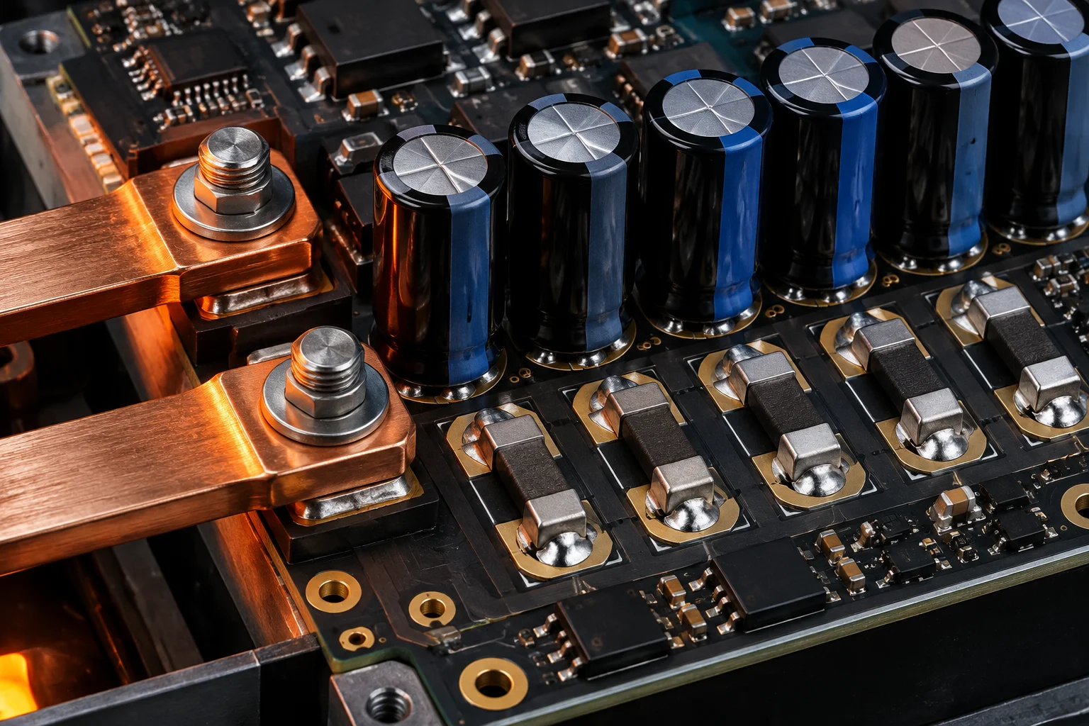 BMS assembly · heavy copper
Questions we get from storage and power-conversion teams
No. We assemble copper busbars, bolted terminals, press-fit pins and heavy-copper planes up to 210 µm, and we do it with selective soldering and recorded torque values. Aluminium ultrasonic wedge bonding needs a different cell, different tooling and a different cleanliness regime; we would rather say that on the first call than quote a process we do not run. If a design depends on aluminium, we will tell you at DFM within 24 hours.
We can integrate a potted or encapsulated assembly where the housing and the material are part of the customer's design, and we know the potting compound's cure schedule and its compatibility with the coating underneath. What we will not do is pot a board and then pretend it is repairable: once a 400 A assembly is potted, a failed shunt means a scrapped unit. That trade-off is written into the DFM report before the first build, not discovered at the first return.
Hipot and isolation-resistance stations are guarded, interlocked and operated by trained staff under a documented procedure, with a forced-discharge step before any board is handled. Test limits, ramp rates and dwell times are fixed in the test specification so a unit is never tested at a voltage someone improvised that shift. The recorded result is part of the lot record and is retained for 10 years, which is what an installer needs when a rack is audited after commissioning.
Send the Gerbers and the current you need to carry
Tell us the continuous bus current, the system voltage class and the copper weight on the drawing. DFM comes back in 24 hours with the profile and stencil consequences already costed.