Through-hole, wave and selective soldering
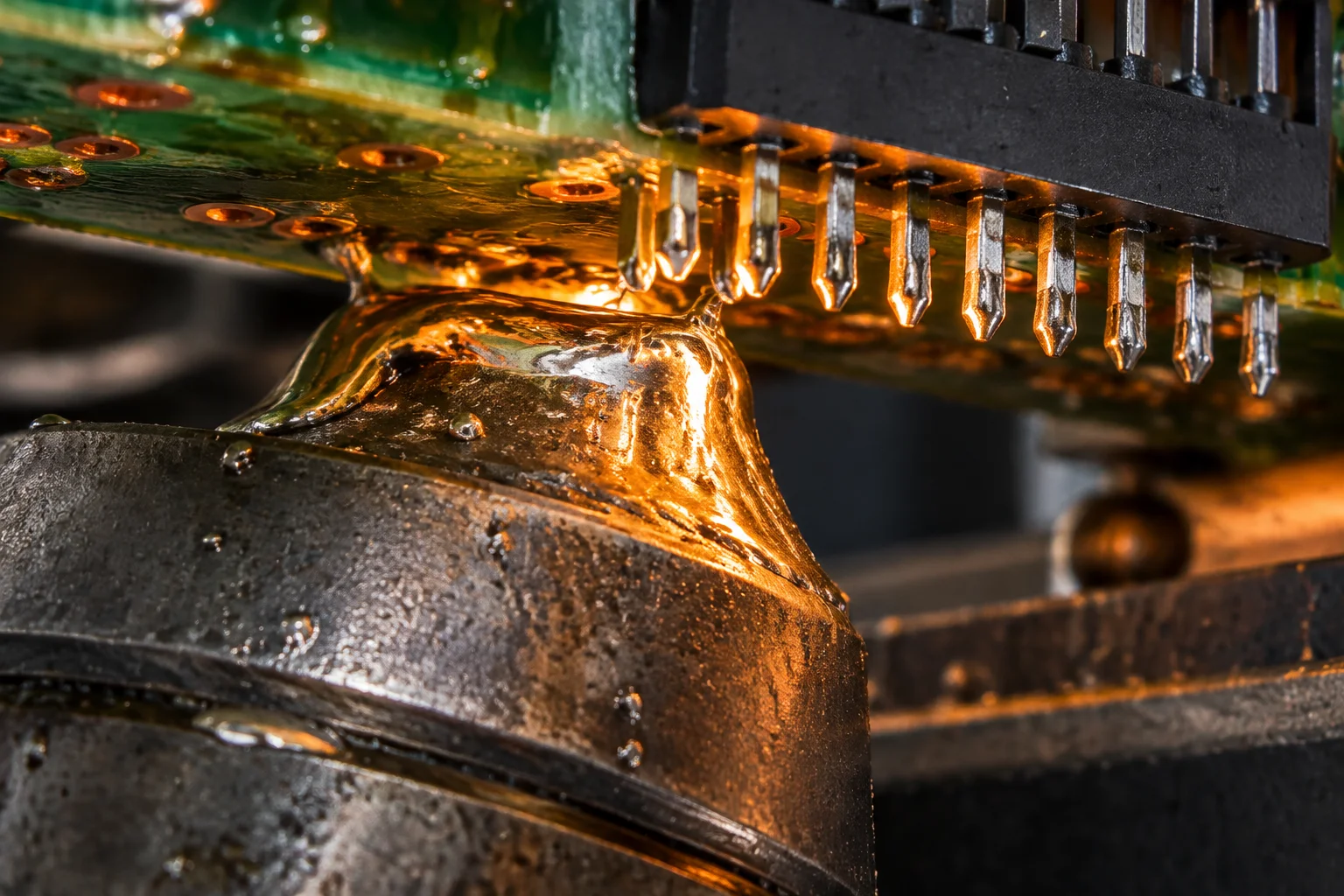
Two nitrogen-inerted wave pots and three selective soldering robots handle the through-hole content that reflow cannot reach: connectors that take mating force, magnetics with real thermal mass, 400 A bus bars and parts that will not survive an oven. Hole fill is held from 0.6 mm to 6.4 mm to IPC-A-610 Class 2 and Class 3 criteria.
- Hole fill range
- 0.6 mm – 6.4 mm
- Wave pots
- 2 · nitrogen inerted
- Selective robots
- 3
- Largest board
- 610 × 510 mm
When through-hole is still the right answer
Through-hole is not legacy work here. It is the correct process for a specific set of joints, and moving those joints to reflow to save a step is how programs end up with cracked barrels and field failures.
Use it for connectors that take repeated mating force: an RJ45, a DIN rail header or a board-to-board block transfers insertion force into the laminate, and a soldered barrel spreads that load through the full board thickness instead of into a surface pad. Use it for magnetics and relays whose thermal mass would not reach liquidus under a reflow profile built for 01005 parts. Use it where vibration is continuous, where a 400 A bus bar has to carry current through a 2 mm barrel, or where the part itself is not reflow rated — most aluminium electrolytics and many sealed relays are not.
The alternative is press-fit, and it is genuinely good for backplanes: a compliant pin needs no solder at all. It also needs a controlled press with force monitoring, a hole tolerance the fabricator must hold, and a repair route that does not destroy the plated barrel. We quote press-fit as tooling plus process, and we will say so when it is the cheaper answer. Where a board is mostly surface-mount with a few soldered joints, the sequence is set on the SMT assembly page.
Wave, selective or hand: which process the joint gets
The choice is driven by joint count, proximity to reflowed parts and how much of the board can be masked. The same panel usually uses two of the three.
| Method | Cycle time | Hole fill | IPC class | NRE |
|---|---|---|---|---|
| Wave, 2 nitrogen pots | 2–4 s in contact | 0.6–6.4 mm, 75 % minimum vertical fill | Class 2 / 3 | Pallet if masking is required |
| Selective, 3 robots | 2–5 s per joint | Localised, full barrel on 0.6–6.4 mm holes | Class 2 / 3 | Programme plus nozzle set |
| Hand soldering and touch-up | 5–15 s per joint | Per IPC-7711/7721 procedure | Class 2 / 3, certified operator | None |
| Pin-in-paste in reflow | No extra pass | ≥ 75 % vertical fill on 1.6 mm boards | Class 2 typical | Stencil aperture change |
High joint count, open layout
Best when a panel has many through-hole joints and enough clearance for a pallet. Contact time is 2–4 s per pass; connectors that cannot be masked go to a selective robot instead.
Fine-pitch SMD already fitted
Three robots with nozzles from 3 mm to 10 mm wet one joint or one row at a time under nitrogen, with the rest of the assembly staying below reflow temperature.
Repair and low-count additions
Certified operators on temperature-controlled irons with recorded tip setpoints. Used for rework, for a handful of joints after selective solder, and for builds where tooling would cost more than the labour.
Barrel fill, fillet acceptance and thermal relief design
Hole fill is a measured quantity, not a visual impression. It is set on the first article by micro-section and then held in process by X-ray and by pot parameters.
Barrel fill and fillet acceptance
Vertical fill is the percentage of the barrel height occupied by solder. Our working floor is 75 % minimum on 0.6–6.4 mm holes for Class 2 and Class 3 work, proven on the first article with a micro-section through the largest thermal mass on the board and then monitored in process by 2D X-ray on the same joint family.
A top-side fillet has to be visible and concave, wetting both the lead and the pad, with no blowholes or pinholes accepted on Class 3 work. On a heavy ground plane the danger is not a missing fillet but a cold one: the barrel looks full and the intermetallic is incomplete, which is why pot temperature and contact time are locked to the profile rather than adjusted per operator.
For 0.6 mm holes the constraint is wicking and blockage — small barrels fill fast and can bridge. For 6.4 mm holes the constraint is thermal: the barrel must be brought to temperature before the wave leaves it, which is why preheat and dwell are set per board thickness.
Thermal relief rules for the design
Ground and power planes connected directly to a through-hole pad pull heat out of the joint. Design the relief with four spokes at 0.25–0.5 mm width and a 0.25–0.4 mm relief gap on inner layers. Wider spokes or a solid connection are fine electrically and a defect generator in production.
Other rules that pay for themselves: leave at least 1.5 mm between a tall component and the joints behind it in the wave direction so the part does not shadow them; orient connectors so solder drains away from the body rather than into it; keep solder thieving pads off high-density areas unless the fabricator has confirmed they are needed; and put a fiducial near any fine-pitch through-hole block so the selective robot can locate it.
We will return annotated markup for all of these in the DFM report. None of them cost money to fix before the boards are fabricated. All of them cost money afterwards.
Flux, preheat and pot chemistry under control
A wave pot is a chemical reactor that runs all day. The parameters below are logged, and a pot that drifts out of them is taken offline rather than topped up and run again.
| Parameter | Set point | Cadence |
|---|---|---|
| Pot temperature | 245–260 °C | Continuous, logged |
| Top-side preheat | 90–120 °C | Per profile |
| Contact time | 2–4 s | Per board thickness |
| Flux specific gravity | Per supplier window | Every shift |
| Dross removal | Per pot, both pots | Every shift |
| Alloy analysis | Copper and contaminant limits | Weekly |
| Nozzle and dross rail clean | Selective nozzles 3–10 mm | Monthly |
| Pot drain and refractory inspection | Full alloy top-up | Every 6 months |
Why the cadence matters more than the set point
Copper dissolves into tin-lead and lead-free alloys as boards run. Past the supplier limit the alloy gets sluggish, fillets turn dull and grainy, and bridging starts on 0.6 mm holes. A weekly analysis catches that drift while it is still a top-up rather than a full pot change.
Dross is removed every shift. Left in place it insulates the wave, changes contact time and drags oxide into the joint. Nitrogen inerting on both pots slows the dross rate substantially, which is why it is standard on this floor rather than an option.
Flux chemistry is matched to the cleaning route. For water-soluble flux, in-line aqueous cleaning follows soldering and the assembly passes an ionic contamination test at or below 1.56 µg NaCl-eq/cm² to J-STD-001. For no-clean flux, the residue is qualified as benign by the flux supplier and the same ionic test is used to prove the board is not too dirty to coat.
Pallets, masking and fixtures: what we build and what we buy
Tooling decides cycle time on every through-hole job. We machine the pallets in-house because the lead time sits on our floor, and we buy the fixtures where a specialist supplier does it better.
Built in-house
Selective solder pallets are machined from high-temperature composite with pockets milled to clear the fitted SMD parts and a mask wall around every joint that must stay dry. The wall is typically 1–1.5 mm thick with a 0.5 mm clearance to the pad so solder cannot climb. Pallets are cut on our own router from the CAD data, which means a design change is a same-week change rather than a supplier lead time.
We also build the masking fixtures: silicone plugs for connector cavities, kapton and machined covers for gold-finger edges, and heat-shield plates that protect an electrolytic can while the joint behind it is soldered.
Bought and qualified
Press-fit tooling is bought: compliant-pin insertion needs a controlled press with force-versus-distance monitoring, and a fixture built by a specialist is cheaper and better instrumented than anything we would machine. Test fixtures follow the same logic — see the test and inspection page.
Every pallet is first-articled before it runs production. The check covers joint fill on the first and last board of the pallet, mask effectiveness on the neighbouring SMD, and pallet flatness, because a warped pallet is the usual cause of a partially filled barrel that appears only on one side of a panel.
Rework and repair to IPC-7711/7721
Rework is a documented process here, not an operator improvising with an iron. Every repair is performed to IPC-7711/7721 and recorded against the board serial number, with the method used, the operator, the tip setpoint and the result.
Typical operations on this floor: removing and replacing a through-hole connector without lifting an inner-layer pad, repairing a damaged barrel with a flared eyelet or a wire splice where the standard permits it, reflowing a cold joint on a heavy ground plane with preheat rather than a hotter iron, and lifting a 0.35 mm pitch BGA with a localised preheater and a controlled profile. Anything that requires a laminate repair is quoted and approved before work starts.
Operators who solder or rework to Class 3 hold current IPC certification and requalify on the 2-year IPC cadence, with an internal re-verification in between. Certification records are available in an audit, and a program can name the operators qualified for its work.
A joint that fails at final inspection is dispositioned by an engineer against the drawing class, and the repair is traced to the board serial number in the MES record. Rework is never used to hide a process defect: a repeat failure mode triggers a process change, not more rework.
Records kept for 10 years
Board-level serialisation, pot logs, alloy analysis results and rework records are held in the MES for 10 years under our IPC-1782 style data retention policy.
Through-hole questions from hardware teams
Usually yes, and it is common on panels with both a dense connector field and a set of large magnetics. The wave pot runs the open area on a pallet; the selective robots handle joints that sit too close to fitted SMD or inside a pocket the pallet cannot mask cleanly. Mixing the two means two tooling items and two process set-ups, so we check at DFM whether a single method is cheaper. If the joint count on one side is small, hand soldering with a certified operator is often the lowest total cost.
Yes, with the right board. Compliant pins need a finished hole tolerance the fabricator can hold, a press with force monitoring, and a repair procedure that protects the plated barrel. We buy the press tooling from a specialist and qualify it on your panel before production. Press-fit removes the soldering step entirely, which is a real advantage on a thick backplane with thousands of pins — but it is not cheaper for a 200-pin board where wave soldering already works.
Where a connector takes insertion force, staking is often the difference between surviving field use and cracking a fillet. Options are an epoxy stake between the housing and the laminate, a screw or compression rivet to a chassis, or a mechanical bracket. All three affect assembly sequence, coating and rework, so they belong in the DFM conversation rather than being added at the end. Underfill and corner-bond materials are qualified against IPC-CC-830 where they also act as a coating.

Send the connector list with the artwork
Joint count, connector height, thermal mass and clearance decide which process your through-hole content should run on. We work it out at DFM and price the tooling with the build.