Industrial automation PCBA: 24/7 duty cycles and a 15-year service life
A machine builder does not buy a board, it buys a maintenance interval. This page sets out the three things that decide whether a controller survives a decade on a plant network — coating integrity, isolation margin and component availability — and the process data we hold behind each one.
- Duty cycle built for
- 24/7 continuous
- Service life planned
- 15 years
- Surge and EFT criteria
- IEC 61000-4-5 / -4-4
- Coating standard
- IPC-CC-830
What actually kills a board on the factory floor
Fifteen years of continuous duty is 131,400 hours of powered operation. Nothing on an automation board wears out from being switched on once. It wears out from the cabinet it lives in.
Thermal cycling comes first. A controller in an unventilated cabinet beside a drive sees a daily swing that a bench prototype never reproduces, and the joints that fail are the ones with the largest mass mismatch: the 55 mm connector, the transformer, the relay. We reflow those on a 12-zone nitrogen profile held to ±1.5 °C repeatability, then inspect the fillets under inline 3D AOI rather than trusting the profile alone.
Humidity and contamination come second. Condensation inside a wash-down enclosure bridges whatever the flux left behind. Residue that is harmless at 2.54 mm pitch leaks across a 0.35 mm gap, so every water-washed lot is sampled to J-STD-001 and released against an ionic contamination result of ≤ 1.56 µg NaCl-eq/cm².
EMI comes third, and it arrives through the wiring rather than the air. 24 V I/O that leaves the enclosure on unshielded cable couples switching noise straight into the logic ground. The fix is layout and coating, not a filter added at the end: we keep the return path under the signal, guard the analogue front end, and coat the assembly so surface contamination cannot turn a creepage path into an antenna.
Fourth is the schedule. A line-down repair window is one shift, and it is the night shift. Anything that needs a re-spin of the bare board rather than a board swap is a production stoppage, which is why the field-replaceable assemblies we build are tested at the box level and serialised before they leave the plant, not after.
A 15-year platform outlives most of its BOM. We plan availability at the assembly level, not the part level: pre-approved alternates, a documented last-time-buy position for the parts that will not survive, and a re-qualification route that does not require the customer to re-open the enclosure design.
The requirement set, written as a build floor
These are the call-outs an automation buyer usually writes into the drawing, and the floor we hold on the line. Where a design cannot reach the floor, DFM says so within 24 hours instead of at first article.
| Requirement | Typical call-out | Our build floor | Why it matters in service |
|---|---|---|---|
| Isolation creepage | 8 mm between mains-side and logic-side copper | 8 mm verified on the assembly drawing | Holds a 2.5 kV hipot margin after coating, not just on a bare board |
| Surge and EFT | IEC 61000-4-5 and IEC 61000-4-4 at system level | Layout and coating rules agreed at DFM | Transient energy leaves the board through copper, not through a component |
| Wide input range | 9 V to 36 V DC nominal rail | Tested at both rails on every lot | A sagging 24 V supply still starts the controller on a cold morning |
| Reverse polarity | Series FET or ideal-diode front end | In-circuit verified per board | Field wiring mistakes cost a fuse, not a programme |
| Relay and opto drivers | 24 V coil, 0.5 A per channel | X-ray on the driver joints | Repeated coil collapse fatigues the joint that carries the inductance |
| DIN-rail mechanics | 35 mm rail clip, board in a 45 mm enclosure | Board edge to 610 × 510 mm panel | Mechanical fit is checked before the enclosure is ordered |
| Board construction | 1.6 mm to 2.4 mm, 2 oz copper on the 24 V rail | 0.4 mm to 6.4 mm overall window | Copper weight sets the thermal rise under continuous load |
| Cleanliness | No visible residue after wash | Ionic ≤ 1.56 µg NaCl-eq/cm² | Residue plus condensation is the shortest path to a field leak |
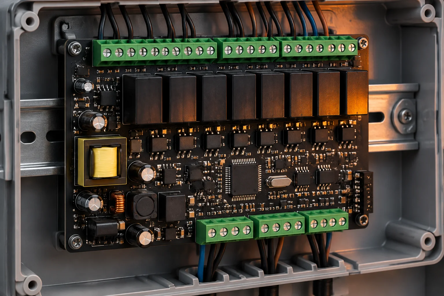 Coated controller assembly · San Jose
Coating, masking and the enclosure decide field failures
The board is the easy part of an automation programme. The barrier between the copper and the plant atmosphere is what fails at year six.
We apply IPC-CC-830 qualified acrylic, polyurethane or silicone by automated selective spray. Acrylic reworks cleanly and suits a controller that may be repaired; polyurethane resists solvent and abrasion on a machine that is washed down; silicone holds flexibility where a 1.5 °C cabinet swing repeats for 15 years. The choice is made at DFM, not after the first field return.
Masking is where coating programmes go wrong. Connectors, press-fit pins, test points and any surface that will later take a screw terminal are masked to a programmed geometry. The keep-out is part of the assembly drawing, so a second build at our Penang plant coats the same way as the first.
Enclosure integration then decides the seal. An IP67 rating on a connector means nothing if the cable gland lets water track onto an uncoated ground pad, and a 24 V field-wiring terminal that is not torque-controlled will loosen under vibration long before the solder does. We build the harness, stake and torque the terminals to a recorded specification, and ship the top-level box with the serial number already applied.
Units that will be repaired in the field are built so they can be: coating rework areas marked, connectors chosen for 30 mating cycles rather than 5, and a board-level test point set that survives being probed after potting.
Keeping a 15-year platform supplied
An automation controller is usually designed once and built for a decade. The sourcing plan has to be written on day one, because the parts that disappear are rarely the expensive ones.
We model annual usage against lifecycle status and hold a last-time-buy position with an MSL baking log and moisture-barrier packing for the parts that go end-of-life mid-programme. 4,000 unique part numbers already sit in the 12,000 sq ft ESD-controlled store.
Every critical line in the BOM gets a cross-reference assessed while the design is still open. Alternate approval is a 24-hour DFM action, not a 12-week engineering change order raised during a shortage.
Board-level serialisation plus MES records let us answer a date-code question ten years after shipment. Records are kept for 10 years in an IPC-1782 style format, which is what a recall-scope or warranty investigation actually needs.
Send the annual volume forecast with the BOM, not after the pilot. A 6,000-unit-a-year programme and a 600-unit-a-year programme get different alternates, different storage commitments and, in some cases, a different board.
Test economics at 500 to 6,000 units a year
High-mix, low-volume automation work cannot carry a bespoke fixture on every part number. The right answer depends on volume, board area and whether the design was laid out for access.
| Method | Coverage | Fixture position | Where it pays |
|---|---|---|---|
| Inline 3D AOI | Placement, polarity, fillet, tombstone | No fixture. 100 % of boards | Every lot, after print, after reflow and post-depanel |
| X-ray and 3D CT | BGA, QFN and LGA voiding | No fixture. Void ≤ 25 % | Any design with a 0.35 mm pitch BGA or a thermal pad |
| Flying probe | Opens, shorts, component values | No fixture. Programming only | Prototypes and 500-unit lots where a fixture never amortises |
| In-circuit test | Nets plus powered cluster tests | Fixture NRE, credited at 5,000 units | Stable programmes above 2,000 units a year |
| Boundary scan (JTAG) | Interconnect on scan-capable devices | Reuses the functional fixture | Dense digital designs with limited test-point access |
| Functional test | The whole product, at temperature if needed | In-house fixture design and build | Anything that ships as a field-replaceable unit |
Fixtures are designed and built in-house, which keeps the loop short when a test escapes: the same engineer who programmed the fixture answers the failure. The customer owns the fixture, the programming and the stencils after first article, and a 40 °C to 125 °C chamber is available for units that need screening rather than a single-pass check.
The document pack that ships with every lot
An automation buyer is usually audited by their own customer. The paperwork has to answer the audit without a phone call to us.
- First article inspection report with X-ray and dimensional data on every NPI
- Certificate of conformance naming the IPC-A-610 class built to
- Ionic contamination result for water-washed assemblies
- Conformal coating record with the material and the keep-out revision
- Serial-number list with date code and reel-level traceability
- Change-notification window before any process or material change
The plant is assessed against ISO 9001:2015 as the base, with ISO 13485:2016, IATF 16949:2016 and AS9100D layered on for the programmes that need them. Workmanship is held to IPC-A-610 Class 2 or Class 3 as specified per assembly, hand soldering and rework follow IPC-7711/7721, and the ESD programme runs to ANSI/ESD S20.20-2021.
Material declarations cover RoHS 2011/65/EU with (EU) 2015/863, REACH SVHC below 0.1 % w/w, and UL 796 laminate recognition for the base material. Conflict-mineral due diligence follows the OECD framework and SEC 13p-1 reporting. Certificate copies are released under NDA on request; we never quote a certificate number in public.
A motor-drive control board, 6,000 units a year for eight years
A drive manufacturer in the Upper Midwest moved a motor-control board to us in 2018 after a field-return cluster traced to coating that stopped short of the connector pins.
The board is a 6-layer, 1.6 mm mixed-technology assembly: 01005 passives on the analogue front end, a 0.4 mm pitch QFN gate driver, three through-hole relays and a 55 mm screw-terminal block. Volume is 6,000 units a year in four releases, which is high enough to justify a functional fixture and low enough that the fixture NRE had to be earned back.
What changed after the transfer: coating keep-outs moved into the assembly drawing, the terminal block went to a torque-recorded press-fit and screw process, and the ionic test result became a lot-release condition rather than a periodic check. First-pass yield at functional test settled in the high nineties and has not moved through three silicon revisions of the gate driver.
The part that mattered most was not process. It was availability. The original gate driver went end-of-life in year four; because an alternate had been cross-referenced and re-qualified during the NPI, the change took a first-article report and one lot of re-verification instead of a redesign.
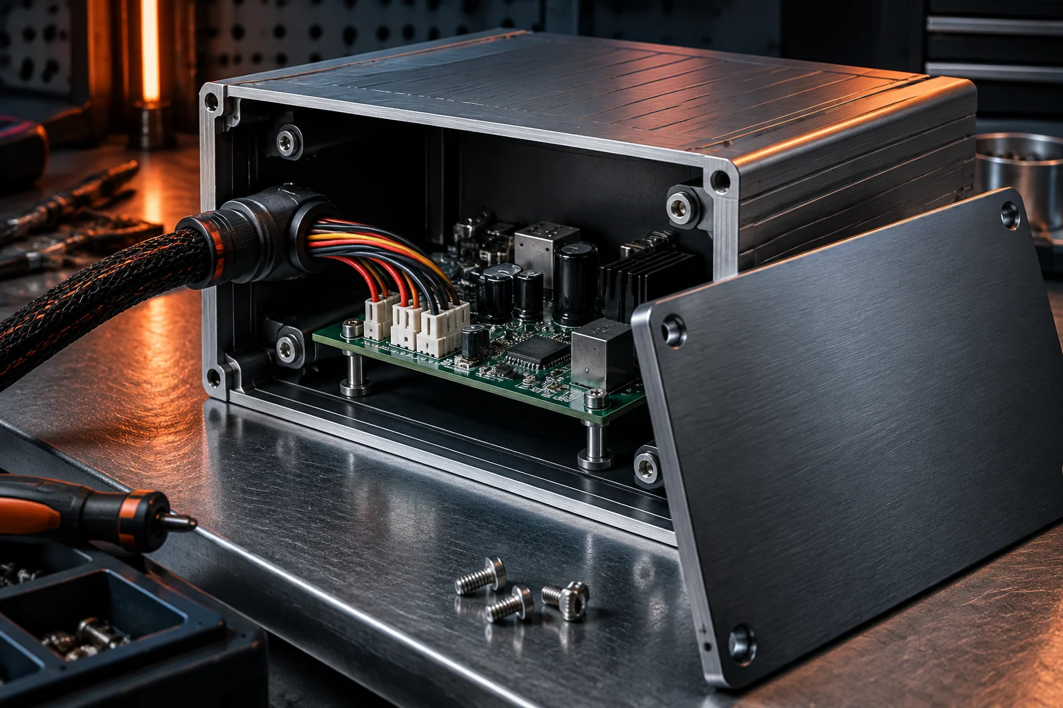 Top-level box · harness and terminals
Questions automation buyers ask before the first build
The three that decide the field failure rate are the electrolytic capacitors, the relay coils and anything with a moving contact. A 105 °C-rated electrolytic rated for 2,000 hours at full ripple is a five-year part in a 70 °C cabinet; derating to half the ripple or moving to a polymer part is a DFM conversation, and it is cheaper than a field campaign. We flag those lines in the DFM report along with the lifecycle status of every active device.
We are a contract manufacturer, not an accredited EMC test house, so we do not issue a compliance report. What we can do is build a pre-compliance unit and run it at a partner lab against the IEC 61000-4-5 and IEC 61000-4-4 criteria your drawing names, which usually finds the layout problems a full scan would charge you a re-test to reveal. The formal certificate stays with the accredited lab.
Give us the serial number. Board-level serialisation and ten years of MES records tell us the build date, the reflow profile, the coating material revision and the reel lots on that unit, so the investigation starts with evidence rather than a guess. Repair and rework follow IPC-7711/7721, and a repaired unit is re-tested against the original functional specification before it goes back. Workmanship is warranted for 12 months.
Send the Gerbers and the service life you are designing for
DFM review in 24 hours, firm quote in 48. Tell us the annual volume up front and the sourcing plan comes back with the price, not after it.