First-pass yield is fixed before the fixture exists
First-pass yield is the share of boards that clear every test gate on the first attempt, without rework, retest or a manual touch. It is a design outcome. By the time a fixture is quoted, the number is already bounded by the placement count, the test point geometry and the coverage the design allows.
The arithmetic is unforgiving because defects accumulate per placement, not per board. Take a board with 1,200 placements and a process running at 30 defects per million placements. The probability that a board carries no defect is (1 − 30 × 10⁻⁶)^1200, which is 96.5 %. To reach 99 % board yield on the same 1,200 placements, the per-placement defect rate has to fall to 8.4 ppm. That is a process problem, and it is solved at the printer and the placement machine — but it is measured at the test fixture, which is why the fixture and the process cannot be planned separately.
Then there is the second half of the number that nobody quotes: final yield after rework. A line can finish at 99.1 % final yield and still have put 60 boards out of 1,000 through a rework bench, each one consuming labour, thermal cycles and a fresh opportunity to damage the assembly. First-pass yield is the number that predicts cost; final yield only predicts shipments.
Test point rules that decide whether a fixture is cheap or impossible
These rules cost nothing at layout and are expensive to retrofit. Every one of them has forced a board respin on somebody's programme.
- P1Test point diameter, 1.0 mm minimumOn a 2.54 mm probe grid, a 1.0 mm pad gives the pin a target with margin for board tolerance and fixture wear. On a 1.27 mm grid, 0.9 mm. Smaller pads mean missed contacts and false failures that look like assembly defects.1.0 mm
- P2Probe pitch, 2.54 mm where you have the room2.54 mm lets the fixture use standard pins and standard blocks. 1.27 mm is available and roughly doubles the fixture cost. Below 1.0 mm pitch, probe access is no longer a practical strategy.2.54 mm
- P3Keep-out, 1.5 mm clear radiusNo component taller than 2 mm within 1.5 mm of a test point on the probed side, and no component under the pin field at all on a vacuum fixture. A single 3 mm tall capacitor in the wrong place turns a fixture into a milled pocket.1.5 mm
- P4One probed side onlyChoose the secondary side and stay there. Double-sided probing requires a flipping fixture or two fixtures, doubles the pin count and roughly triples the cost and the maintenance burden.1 side
- P5Nothing under a shield can, connector or battery holderIf a test point is unreachable once the assembly is built, it is not a test point. Move it to the probed side at layout, or it will be dropped from coverage and never mentioned again.Reachable
Two more details worth writing into the layout notes. Solder-mask openings over test points should be at least 0.1 mm larger than the copper pad, or mask residue builds on the probe tip and contact resistance climbs over a shift. And test points should be connected to the net with a short trace rather than sharing a pad with a component lead, so that probing does not load a solder joint mechanically.
Flying probe, in-circuit and functional: cost per board at three volumes
The three strategies are not ranked; they are priced against volume. Flying probe needs no fixture, so it has almost no non-recurring cost and a high per-board cost because the machine moves slowly. In-circuit test needs a bed-of-nails fixture, so it carries a five-figure non-recurring cost and a low per-board cost. Functional test needs a fixture plus a harness and a loaded test sequence, which lands between the two.
Worked at a machine rate of $120 per hour — the fully loaded cost of a test cell, including operator, calibration and floor space:
| Strategy | Fixture NRE | Test time | At 50 boards | At 500 boards | At 5,000 boards |
|---|---|---|---|---|---|
| Flying probe | $0 | 6 min | $600 | $6,000 | $60,000 |
| In-circuit test | $9,000 | 45 s | $9,075 | $9,750 | $16,500 |
| Functional test | $18,000 | 120 s | $18,200 | $20,000 | $38,000 |
The break-even between flying probe and in-circuit test is 857 boards: at 12 × N against 9,000 + 1.5 × N, the two are equal at N = 857. Below that, flying probe is cheaper and needs no fixture lead time. Above it, the fixture wins and keeps winning.
The comparison moves again because fixture NRE is credited at 5,000 units on a production programme, which removes the non-recurring cost from the 5,000-board column entirely and makes in-circuit test cheaper still at that volume. For a programme that may never pass 500 boards, that credit is worth nothing, and a five-figure fixture is capital sitting on a shelf — which is why the honest answer at prototype volume is often flying probe plus a small functional check, with the fixture deferred until the volume is contracted.
Volume decides the strategy, but coverage decides the yield. A cheap test that misses a failure mode is a false economy: a board that escapes test and fails at the customer costs a return, a failure analysis, a corrective action and a schedule, all of which dwarf the per-board test saving.
Pogo budget, probe force and board support
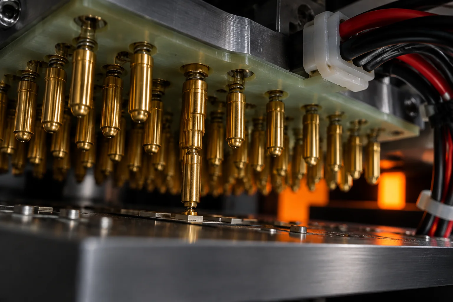
A bed-of-nails fixture is a spring array pushing against a board, and the board has to survive it. Each spring probe typically needs 2 to 3 ounces of contact force, which is 0.6 to 0.9 newtons. The forces add up fast.
A 500-probe fixture at an average of 2.5 oz per probe applies 1,250 oz — about 35 kg, or 78 lb, distributed across the board. That load is applied every test cycle, thousands of times. A 1.0 mm thick board with no support under a large BGA will flex under it, and the flex cracks the very joints the fixture is trying to verify. Board support posts and a vacuum plate are not optional extras on a fixture of that size.
The probe budget is a design constraint, not a purchasing list. Spring probes are specified for 100,000 to 1,000,000 cycles depending on grade, and the spring force falls off long before the pin fails electrically. We re-verify spring force at every 50,000 cycles and retire a probe when it drops below 2 oz, because a low-force pin gives an intermittent contact that reads as a random assembly failure and wastes a day of failure analysis. Wiper-action and spear-point geometries are chosen per pad type: spear for a via, crown for a plated pad, and no sharp geometry on a test pad that will later be coated.
Support geometry matters equally. Posts go under connectors, under the heaviest components, and around the board perimeter; the vacuum plate gasket is checked for compression before every fixture qualification. A fixture that bends the board by 0.2 mm on every cycle is a reliability test nobody designed.
Boundary scan: what it covers and what it never will
Boundary scan, defined by IEEE 1149.1 and usually called JTAG, turns a device's own I/O pins into a test access port. It costs nothing to use if the devices on the board have the cells and the chain is routed to an accessible header, and it can replace a hundred test points that would otherwise need a fixture.
What it covers well: interconnect between scan-capable devices, opens and shorts on those nets, and the presence of a device that responds on the chain. What it never covers: power rails, which have no scan cell; analog nodes and anything upstream of an ADC; nets that terminate only in passive components; connectors without scan cells; and anything about the mechanical or thermal assembly, because the chain tests the silicon, not the joint.
Coverage is therefore a number to be reported, not assumed. A practical board with four scan-capable devices typically reaches 40 % to 70 % of nets, and the honest way to use that is to compute the net list coverage against the fault spectrum and then decide which of the remaining nets need physical probes. Where a scan chain is present, it usually pays for itself by removing 30 to 40 test points from the fixture, which reduces probe force, pin count and fixture cost at the same time.
What to include in a test specification
A test specification is a document the customer signs, not a programming note. Without it, the fixture gets built to the engineer's interpretation and the first production lot discovers the difference.
- Every measurement with its nominal, its pass limit and its fail limit, including the units
- The test sequence and what happens when a step fails — stop, or continue and log
- Coverage statement: which nets and which functions are tested, and which are not
- Retest policy: how many attempts are allowed before a board is routed to failure analysis
- Firmware and software revisions the test depends on, pinned, not “latest”
- Environmental conditions for the test: ambient, supply voltage tolerance, load
- Calibration interval for the fixture and its instruments, and the record that proves it
- Gauge repeatability target for the critical measurements, with the measurement method
- Fixture identifier and serialised board traceability, retained for 10 years under IPC-1782-style records
Two of these get skipped most often and cost the most. The retest policy matters because unlimited retesting hides a genuine defect until it reaches a customer. The gauge repeatability target matters because a test that is not repeatable produces failures the process engineer cannot act on — if the same board measures differently on two consecutive runs, the limit is wrong or the fixture is.
We run functional fixtures with a golden board and a deliberate fault check as part of the qualification, so that a fixture failure is separated from an assembly failure before the line is allowed to run. Boundary scan, in-circuit test and flying probe are all available in-house, and the choice between them is made against your volume and fault spectrum rather than against a preference.
Fixture ownership and transfer
Tooling ownership is one of the first commercial questions a hardware lead asks, and the answer is simple: the customer owns the stencils, the test fixtures and the programming after the first article. That ownership is only worth something if the transfer package is complete, and a fixture without documentation is a box of pins.
- Mechanical: the fixture drawing, the probe list with part numbers, the support post layout and the vacuum plate detail.
- Electrical: the wiring schedule, the interface connector pinout, the instrument list and the calibration certificates.
- Software: the test program source, the sequence file, the limit file and the version history, with a note on which development environment builds it.
- Records: the qualification report, the golden-board result, the gauge study and the maintenance log.
A transfer to another manufacturer without those four sets means rebuilding the fixture from scratch, which is a five-figure cost and a four to six week schedule on a programme that usually cannot afford either. We hold fixtures and their documentation for the life of the programme and release copies on request; fixture NRE is quoted separately and credited at 5,000 units, so a programme that scales is not paying twice for the same access.
The cheapest fixture is the one the layout did not need. Reserve the test points, keep them on one side, keep 1.5 mm clear around each, and bring a test specification to the first design review. That is a two-hour conversation at layout and a five-figure saving at production.
Takeaways
- 1,200 placements at 30 ppm per placement gives 96.5 % board yield; 99 % needs 8.4 ppm.
- Test points: 1.0 mm diameter on a 2.54 mm grid, 0.9 mm at 1.27 mm pitch, probed on one side only.
- Keep 1.5 mm clear around every test point and never place one under a shield, connector or holder.
- At a $120 per hour cell rate, flying probe costs $600 at 50 boards and in-circuit test costs $9,075 — the break-even is 857 boards.
- At 5,000 boards, in-circuit test is $16,500 against $60,000 for flying probe, before the NRE credit.
- A 500-probe fixture at 2.5 oz per probe applies about 35 kg of force; support the board or it will flex and crack joints.
- Retire a probe when spring force falls below 2 oz, not when it fails electrically.
- Boundary scan covers 40–70 % of nets on a typical scan-capable design and never covers power rails or analog nodes.
- Write the retest policy and the gauge repeatability target into the test specification, or the failures are unactionable.
- Fixture ownership means nothing without the mechanical, electrical, software and qualification package.