Why print decides yield before the first placement
Across the SMT defects we scrap and rework, roughly 60–70 % trace back to the paste deposit, not to the placement head. The reason is simple arithmetic: a placement machine either puts a part on a pad or it does not, and both outcomes are visible to inline 3D AOI. A paste deposit that is 40 % light on volume still looks like a deposit. It wets, it pulls the part down on one side, and it produces a joint that passes visual inspection and fails a thermal-cycle test eleven months later.
That is why we measure the process input rather than only the output. Every board that enters a FLASHPOINT SMT line runs through 3D SPI after printing and inline 3D AOI after reflow, and the SPI data is the first thing a process engineer looks at when a build drifts. A paste volume distribution tells you which of four knobs to turn in the next ten minutes: the stencil, the squeegee, the paste, or the printer setup. Guessing between them costs a shift.
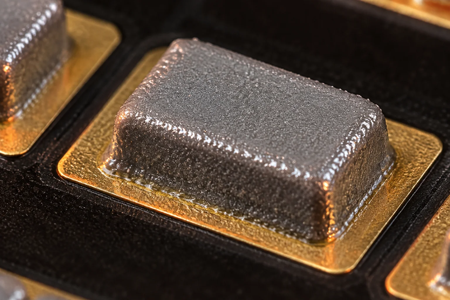
Nothing downstream can recover the volume. Reflow will not add solder, and a touch-up iron adds flux and thermal load rather than a repeatable fillet. The deposit you print is the joint you ship.
The arithmetic of paste volume: area ratio and transfer efficiency
Aperture design is governed by the area ratio, which is the area of the aperture opening divided by the area of the aperture walls. For a square aperture of side L and stencil thickness t, the area ratio is L² / (4·L·t). IPC-7525 puts the design floor at 0.66 for a stencil printing process with good release; below that, paste preferentially sticks to the aperture wall and the deposit comes out short and rounded.
Run the numbers on real pads. A 0.4 × 0.4 mm QFN land has an aperture area of 0.16 mm². On 0.10 mm foil the area ratio is 1.00. On 0.12 mm foil it is 0.83. On 0.15 mm foil it drops to 0.67 — sitting on the IPC-7525 floor with nothing left for process variation. On 0.20 mm foil it is 0.50, and the process will not run without either a stepped stencil or a smaller aperture than the customer drew.
Now convert the ratio into the number that actually matters. The nominal deposit volume is aperture area times foil thickness: 0.16 mm² × 0.12 mm = 0.0192 mm³, which is 19.2 nL of paste on one QFN pad. With a well-behaved process the transfer efficiency lands between 80 % and 95 %, so you deposit somewhere between 15.4 nL and 18.2 nL. Your SPI limit is not the nominal, it is the window you accept around it: we gate at ±10 % of nominal volume, which for this pad is 17.3 nL to 21.1 nL.
| Square pad | Aperture area | 0.10 mm foil | 0.12 mm foil | 0.15 mm foil | 0.20 mm foil |
|---|---|---|---|---|---|
| 0.25 mm (01005 land) | 0.0625 mm² | 0.63 | 0.52 | 0.42 | 0.31 |
| 0.40 mm (QFN land) | 0.16 mm² | 1.00 | 0.83 | 0.67 | 0.50 |
| 0.50 mm (0402 land) | 0.25 mm² | 1.25 | 1.04 | 0.83 | 0.63 |
| 0.80 mm (0603 land) | 0.64 mm² | 2.00 | 1.67 | 1.33 | 1.00 |
Read the table like a design review. The 01005 land fails the floor on every foil we run, which is why an 01005 aperture is printed with a controlled overprint: enlarge the aperture to 0.27 × 0.27 mm and the area ratio rises to 0.68 on 0.10 mm foil, while the extra 0.02 mm per side stays inside the solder-mask opening. The 0.40 mm land is comfortable at 0.12 mm and marginal at 0.15 mm — so on a mixed board with 0.5 mm pitch connectors that want 0.15 mm foil, the QFN apertures get stepped down or the whole stencil goes to 0.12 mm with a step-up pad-side.
One more number to keep in view: the printer moves paste, not solder. The deposit loses roughly 50 % of its volume as flux volatiles and shrinkage during reflow. A 19.2 nL deposit produces a fillet on the order of 9–10 nL of solid solder, which is what your IPC-A-610 Class 2 or Class 3 fillet is actually made of.
Stencil specification: foil, coating, stepping and tension
We cut laser stainless steel, nano-coated, in 0.10 mm to 0.20 mm foil, with a four-hour turn from a Gerber release. The specification that gets sent to the laser is not a single thickness for the whole panel — it is a per-region decision driven by the area-ratio table above.
- 0.10 mm for 01005, 0.3 mm CSP and 0.35 mm pitch BGA. Thin foil protects the area ratio and reduces the paste volume on fine-pitch apertures, at the cost of slumping on large pads.
- 0.12 mm for mixed boards where 0402, 0.4 mm QFN and 0.5 mm pitch connectors share a panel. This is the thickness that satisfies the most aperture sizes at once, which is why it is our default.
- 0.15 mm for through-hole reflow, 0603 and larger, and power boards where the paste volume needs to fill a thermal pad.
- 0.20 mm only where the smallest aperture on the panel is 0.6 mm or larger. Below that, transfer efficiency drops off and the paste deposit becomes a rounded brick.
Nano-coating is not cosmetic. A coated foil lowers the friction between the paste and the aperture wall, which raises transfer efficiency by roughly 5–10 percentage points on fine-pitch apertures and widens the release window. On a 0.4 mm QFN aperture at an area ratio of 0.67, that is the difference between a deposit inside the ±10 % window and a deposit that runs 15 % light all shift.
Tension matters more than most packages allow for. A framed stencil should sit between 35 N/cm and 50 N/cm measured at the centre. Below 30 N/cm the foil lifts with the board on separation, paste smears across the underside, and the next print picks up the smear. We check tension at goods-in and re-check at 10,000 print cycles; a foil that has lost 20 % of its tension is retired, because no squeegee setting will compensate for a foil that moves.
Step stencils solve the mixed-thickness problem in one tool: 0.12 mm in the fine-pitch region, stepped up to 0.18 mm over a connector or a thermal pad. The step is a stress riser, so we keep the transition at least 2 mm clear of any aperture and specify the step direction on the fabrication drawing rather than leaving it to the stencil house.
Squeegee, speed, pressure and separation
Four printer settings move paste volume, and only one of them should be touched during a running shift.
- Print speed, 25–75 mm/s. Slower fills the aperture more completely, especially at high area-ratio contrast across the panel. Faster reduces paste shear and increases the chance of voids in the deposit. We run 30–50 mm/s on fine-pitch panels.
- Squeegee pressure, 3.5–6.0 kg on a 300 mm blade. That is roughly 0.12–0.20 kg per centimetre of blade. Too little pressure leaves paste on the foil; too much drives paste under the stencil and prints a halo around fine-pitch apertures. Pressure is set to clean the foil, not to push paste through it — the aperture fill happens ahead of the blade, not under it.
- Separation speed, 0.5–3 mm/s. The single most under-set parameter on a printer. A slow, controlled separation lets the paste release from the aperture wall; a fast separation tears the deposit and produces the classic dog-eared fine-pitch print.
- Blade type. Metal blades for fine pitch, 0.4 mm QFN and 01005 at 60–90 durometer polyurethane for coarse work, where a metal blade wears the foil faster than it improves the deposit.
The environment is part of the setting. We hold the print room at 23 ± 2 °C and 40–60 % relative humidity. Below 40 % RH the paste flux dries on the stencil between wipes and the deposit volume falls over a shift; above 60 % RH the paste takes on moisture and slumps on the large pads.
Paste handling has its own clock. Type 4 paste (20–38 µm particle size per J-STD-005) is stored at 2–10 °C with a shelf life of six months, warmed sealed for at least two hours before opening to avoid condensation, and used within eight hours on the stencil. Type 5 (15–25 µm) is what 01005 and 0.3 mm CSP work needs; it is more sensitive to drying and gets a shorter working life. Paste that has been on the stencil for eight hours is not extended with fresh paste as a habit — it is scraped and replaced, because mixing aged and fresh paste makes the deposit distribution bimodal and hides the real process variation from SPI.
What SPI data actually shows, and how to act on it
SPI reports four things per aperture: volume, area, height and XY offset. Volume is the one that predicts defects; the other three tell you why the volume is off. A deposit with correct volume but low height and large area means the aperture is over-sized and the paste is spreading. Correct area with low height means the aperture is not filling — a pressure or speed problem. Correct height with an XY offset means the stencil is not registered to the board, which is a tooling problem rather than a paste problem.
We gate every printed board at ±10 % of nominal volume and hold CpK ≥ 1.67 against those limits, which is the same statistical gate we apply across the SMT process. CpK is the distance from the process mean to the nearer specification limit, divided by three standard deviations. It punishes an off-centre process and a variable one, and it makes the difference between them obvious.
Nominal volume 0.0192 mm³ (19.2 nL). Specified window 17.3 nL to 21.1 nL. Measured mean 19.5 nL — nicely centred — with a standard deviation of 0.7 nL. CpK = min[(21.1 − 19.5) / 2.1, (19.5 − 17.3) / 2.1] = min[0.76, 1.05] = 0.76. The process is centred and still fails the 1.67 gate, because it is too variable. To reach 1.67 on the same mean, the standard deviation has to come down to 0.32 nL — less than half. No amount of tweaking the squeegee pressure does that; it needs a stencil or paste change.
That is the useful discipline of the number. A CpK below 1.00 usually points at the tooling: a worn foil, an aperture that was laser-cut 15 % oversize, a stencil that has lost tension. A CpK between 1.00 and 1.67 with a stable mean points at paste behaviour — aging on the stencil, or an environment that is out of window. A drifting mean with a tight distribution points at the printer itself: blade wear, a worn rail, or a board support that lets the panel flex under the blade.
When CpK drops: what to change first
Three actions resolve most in-shift volume excursions, in this order.
- First, five minutes
Wipe the stencil underside and reset the wipe cycle
Paste that has transferred to the underside of the foil lifts the stencil off the board on the next print, which increases the gap and reduces the deposit. We wipe dry every 5 prints and run a vacuum-assisted wipe every 10, with a solvent wipe at each paste change. If SPI volume has fallen 8 % in an hour with no other change, look under the stencil before you touch a setting.
- Second, ten minutes
Check paste age, temperature and kneading
A jar that came out of the refrigerator 45 minutes ago is still cold and will print light. Paste that has been open for more than eight hours has dried enough to shift the mean. And paste that has been sitting unstirred separates: flux rises and the deposit prints heavy on flux, light on alloy.
- Third, tooling
Change the foil, not the settings
If volume is stable but consistently 10–15 % light on fine pitch alone, the aperture geometry or the foil thickness is wrong for the pad. Move the fine-pitch region to 0.10 mm foil, add a controlled overprint for the 01005 land, or step the stencil. A process window pushed to the edge of the area-ratio floor does not get fixed by running the printer slower.
The thing that does not work is raising squeegee pressure. Pressure is already set to clear the foil; adding more drives paste under the stencil, produces a halo around fine-pitch apertures, and increases bridging on 0.4 mm QFN without raising the deposit volume. We see this attempted on roughly every second line audit and it costs a shift to undo.
What to put in the DFM package so print is designed, not tuned
Print problems are cheapest to solve on a screen. A DFM package that carries the following lets us check area ratios before a stencil is cut, rather than after the first panel is scrapped.
- Gerber or ODB++ with the paste layer drawn at final aperture size, not at land size
- Board thickness and stackup, because stencil stepping depends on it
- The finest pitch and the smallest chip on the board, named explicitly
- Largest thermal pad or connector pad with its paste-coverage intent
- Mixed-technology notes: which through-hole parts are reflowed, which are wave soldered
- Surface finish and solder-mask opening, since both change release
- Annual volume, because it decides whether a stepped stencil is worth the tool cost
- The standard you want the assembly held to: IPC-A-610 Class 2 or Class 3
Send a BOM with the Gerber set and the DFM review comes back in 24 hours with the area-ratio table for your own apertures, the foil thickness we recommend per region, and any aperture we would change before cutting steel. A firm quote follows in 48 hours. Prototype quantities start at 5 boards, and the stencil is fabricated in four hours from the final release, so an aperture change costs a day, not a week.
Takeaways
- Roughly 60–70 % of SMT defects trace to the paste deposit, and nothing downstream recovers lost volume.
- IPC-7525 sets the area-ratio floor at 0.66. Compute it per aperture, not per board.
- A 0.4 mm QFN land gives an area ratio of 0.83 on 0.12 mm foil and 0.67 on 0.15 mm foil — the second one has no margin.
- An 01005 land needs a controlled overprint to 0.27 mm to clear the floor on 0.10 mm foil.
- Gate SPI at ±10 % of nominal volume and CpK ≥ 1.67 on 100 % of boards.
- A centred process with σ = 0.7 nL scores CpK 0.76; reaching 1.67 needs σ = 0.32 nL, which is a tooling fix.
- Wipe the stencil underside every 5 prints; a dirty foil costs more volume than a wrong pressure setting.
- Store Type 4 paste at 2–10 °C, warm it sealed for 2 hours, and use it within 8 hours on the stencil.
- Send the paste layer at final aperture size and get the area-ratio check before the stencil is cut.